
Interoperability Test System for EPC
Compliant Class-1 Generation-2 UHF
RFID Devices
INTEROPERABILITY TEST METHODOLOGY
Version 1.2.4
Date: 2006-06-27 Version 1.2 Page 1 of 84

Interoperability Test System for EPC compliant Class-1 Gen-2 UHF RFID
Revision History
Revision Date Comments
0.1 2004-11-15 First release
2.0 2005-03-17 Major changes
3.0 2006-05-29 Replaced sections 6 and 7, revising list of test cases and introducing
scripting requirements as a means for rapid and thorough testing
3.1 2006-06-02 Merged all annexes and added printer requirements
1.0 2006–06-09 Restarted Revision Number - Removed CETECOM Logo Rearranged
some sections
1.1 2006-06-15 Revised Document for Editorial and Structural Changes
1.2 2006-06-27 Updated section 6, clarifying and reorganizing test cases with some
modifications made to the scripting syntax
1.2.2 2006-07-26 Put further clarification into the Lock/PermLock command set.
Replaced PU_AP_L_1 and PU_AP_L_2 with PL_ AP_L_1 and
PL_AP_L_2 because these commands were taken care of by other
test cases. Added PU_E_PU, PU_T_PU and PU_U_PU to test these
failing cases. Corrected SQ_E_S3_8 pointer. Updated SQ command.
1.2.3 2006-08-03 Revised Select/Query Test Cases table for pointer and length specs.
1.2.4 2006-08-04 Revised for editorial change to Select/Query Test Cases table.
Contributors
Rosario Trapero, CETECOM, Spain
Mª José Rodríguez CETECOM, Spain
Vince Moretti Impinj, USA
Hoosamuddin Bandukwala MET Laboratories, USA
Gaylon D. Morris MET Laboratories, USA
Disclaimer and copyright notice
THIS DRAFT DOCUMENT IS PROVIDED “AS IS” WITH NO WARRANTIES
WHATSOEVER, INCLUDING ANY WARRANTY OF MERCHANTABILITY,
NONINFRINGEMENT, FITNESS FOR ANY PARTICULAR PURPOSE, OR ANY
WARRANTY OTHERWISE ARISING OUT OF ANY PROPOSAL, SPECIFICATION OR
SAMPLE. Any liability, including liability for infringement of any proprietary rights, relating to
use of information in this document is disclaimed.
No license, express or implied, by estoppels or otherwise, to any intellectual property rights are
granted herein.
Date: 2006-08-04 Version 1.2.4 Page 2 of 84

Interoperability Test System for EPC compliant Class-1 Gen-2 UHF RFID
Date: 2006-08-04 Version 1.2.4 Page 3 of 84

Interoperability Test System for EPC compliant Class-1 Gen-2 UHF RFID
Table of Contents
1.0 Scope...................................................................................................................................7
2.0 References ..........................................................................................................................7
3.0 Definitions and Abbreviations..........................................................................................8
3.1 Definitions ..............................................................................................................8
3.2 Abbreviations.........................................................................................................9
4.0 Procedures........................................................................................................................10
4.1 Procedures............................................................................................................10
5.0 Test Suite Design..............................................................................................................11
5.1 Test Suite Overview.............................................................................................11
5.2 Test Cases.............................................................................................................12
6.0 Scripting Language .........................................................................................................21
6.1 Script Language Syntax......................................................................................21
6.2 Script File Example.............................................................................................31
6.3 Output File Example...........................................................................................31
7.0 Test Sites...........................................................................................................................34
7.1 General Characteristics ......................................................................................34
7.2 Multiple-tag Setup...............................................................................................34
7.3 Test Sites for Interoperability ............................................................................35
7.4 Qualified Equipment...........................................................................................37
7.5 Test System Validation........................................................................................37
A.1 Scope................................................................................................................................38
A.2 References .......................................................................................................................38
A.3 Definitions .......................................................................................................................38
A.4 Abbreviations..................................................................................................................38
A.5 Conformance to this IS proforma specification...........................................................38
A.6 Guidance for completing the IS proforma....................................................................39
A.6.1 Purposes and structure .......................................................................................39
A.6.2 Abbreviations and conventions ..........................................................................39
A.6.3 Instructions for completing the IS proforma....................................................40
A.6.4 Identification of the implementation .................................................................40
A.6.5. Roles.....................................................................................................................42
A.7 Operating Parameters.....................................................................................................48
B.1 Test Laboratory...............................................................................................................50
B.2 Client.................................................................................................................................51
B.3 Manufacturer...................................................................................................................51
B.4 Implementation Under Test............................................................................................52
B.5 Implementation Under Test 2.........................................................................................52
B.6 Testing Environment.......................................................................................................53
B.7 Means of testing identification:......................................................................................53
B.8 Test conditions:................................................................................................................53
B.9 Limits and reservations...................................................................................................54
B.10 Record of agreement .......................................................................................................54
B.11 Iut Conformance Status..................................................................................................55
B.12 Static Conformance Summary.......................................................................................55
B.13 Dynamic Conformance Summary..................................................................................55
B.14 Static Conformance Review Report...............................................................................55
B.15 Test Campaign Report....................................................................................................56
Date: 2006-08-04 Version 1.2.4 Page 4 of 84

Interoperability Test System for EPC compliant Class-1 Gen-2 UHF RFID
B.16 Observations ....................................................................................................................56
C.1 Manufacturer Data..........................................................................................................57
C.2 Manufacturer Identification...........................................................................................58
C.3 Reference from EPCglobal Gen 2 Specification...........................................................59
C.4 Test Suit Structure ..........................................................................................................60
C.5 TP Naming Convention...................................................................................................62
C.6 Test Case Procedures ......................................................................................................63
D.1 Qualified Equipment.......................................................................................................71
D.2 Definitions of Interoperability Testing Terms:.............................................................72
D.3 Selection of QE.................................................................................................................73
D.4 Evaluation of the products..............................................................................................73
D.5 Test Equipment................................................................................................................74
D.6 Test Equipment................................................................................................................77
D.7 Hardware Description.....................................................................................................78
D.8 Test Manager and Sequencer Modules .........................................................................78
D.9 Running Individual Test Cases ......................................................................................82
Date: 2006-08-04 Version 1.2.4 Page 5 of 84

Interoperability Test System for EPC compliant Class-1 Gen-2 UHF RFID
Tables
Table 1. Approximate Test Case Identifier ..................................................................................12
Table 2. Kill Password Test Cases ...............................................................................................13
Table 3. EPC Memory Test Cases................................................................................................14
Table 4. TID Memory Test Cases ................................................................................................15
Table 5. User Memory Test Cases ...............................................................................................16
Table 6. Access Test Cases...........................................................................................................18
Table 7. Select/Inventory Test Cases ...........................................................................................18
Table 8. Select/Query Test Cases.................................................................................................20
Table 9. Select/ Query Action ......................................................................................................20
Table A.1. Roles............................................................................................................................42
Table A.2. Basic operations and capabilities for managing tag populations................................42
Table A.3. Commands supported.................................................................................................43
Table A.4. Memory banks supported ...........................................................................................44
Table A.5. Stored passwords in Reserved memory bank.............................................................44
Table A.6. Stored data in EPC memory bank ..............................................................................44
Table A.7. Object identifier type..................................................................................................44
Table A.8. Stored data in TID memory bank................................................................................45
Table A.9. States............................................................................................................................45
Table A.10. Commands supported................................................................................................46
Table A.11. Logical partitioning of the memory banks ................................................................46
Table A.12. Memory locations of stored data in each memory bank............................................47
Table C.1 Manufacturer product summary....................................................................................58
Table C.2 Test Cases List Reference............................................................................................61
Figures
Figure 1. Multi-tag Board.............................................................................................................35
Figure 2. Test Site 1......................................................................................................................35
Figure 3. Test Sites 2 and 3 ..........................................................................................................36
Date: 2006-08-04 Version 1.2.4 Page 6 of 84

Interoperability Test System for EPC compliant Class-1 Gen-2 UHF RFID
1.0 Scope
This document specifies the design of an Interoperability test system for testing that end-to-end
functionality between two communicating RFID hardware devices as required by “EPC
TM
Radio-Frequency Identity Protocols Class-1 Generation-2 UHF RFID Protocol for
Communications at 860 MHZ – 960 MHz. Version 1.0.9”.
The RFID devices under test are interrogators, also known as readers, printers, also known as
encoders, and one or more tags, also known as labels. Tags can be passive, meaning that they
receive all of their operating energy from the interrogator’s RF waveform. They can also be
semi-passive, or active provided the utilized integrated circuit (IC) is compliant to the above
referenced specification. The protocol is interrogator-talks-first (ITF), meaning that a tag
modulates its antenna reflection coefficient with an information signal only after being directed
to do so by an interrogator.
2.0 References
The following documents contain provisions which, through reference in this text, constitute
provisions of the present document.
• References are either specific (identified by date of publication, edition number,
version number, etc) or non-specific.
• For a specific reference, subsequent revisions do not apply.
• For a non-specific reference, the latest version applies.
[1] EPCglobal, Inc.
“EPC
TM
Radio-Frequency Identity Protocols Class-1 Generation-2 UHF
RFID Protocol for Communications at 860 MHZ – 960 MHz. Version 1.0.9”, December
2004.
[2] EPCglobal, Inc.
“EPC
TM
Tag Data Standards”
[3] EPCglobal
TM
(2004): FMCG RFID Physical Requirements Document (draft)
[4] ISO/IEC 15961: Information technology-Radio frequency identification (RFID) for item
management-Data protocol: application interface.
[5] ISO/IEC 15962: Information technology-Radio frequency identification (RFID) for item
management-Data protocol: data encoding rules and logical memory functions.
[6] ISO/IEC 15963: Automatic Identification- Radio Frequency Identification for item
management-Unique identification for RF tag.
[7] ISO/IEC 9646-1: Information technology - Open Systems Interconnection - Conformance
testing methodology and framework - Part 1: General concepts.
[8] ISO/IEC 9646-2: Information technology - Open Systems Interconnection - Conformance
testing methodology and framework - Part 2: Abstract Test Suite specification.
[9] ETSI ETS 300 406: Methods for Testing and Specification (MTS); Protocol and Profile
Conformance Testing specifications; Standardization methodology.
[10] ETSI TS 102 237-1 v 4.1.1 (2003-12): Telecommunications and Internet Protocol
Harmonization Over Networks (TIPHON) Release 4; Interoperability test methods and
approaches; Part 1: Generic approach to interoperability testing.
[11] Interoperability Test System for EPC compliant devices Class-1 Generation-2 UHF RFID
devices. Requirements for the Interop tester v1.0 CETECOM
Date: 2006-08-04 Version 1.2.4 Page 7 of 84

Interoperability Test System for EPC compliant Class-1 Gen-2 UHF RFID
3.0 Definitions and Abbreviations
3.1 Definitions
For the purposes of the present document, the following terms and definitions apply:
Interoperability: Ability of two or more systems or devices to exchange information using the
same communication protocol.
Interoperability testing: Activity of testing end-to-end functionality between (at least) two
communicating systems as required by the standard(s) on which those systems are based.
Reference specification: A standard, which specifies a base specification, or a set of base
specifications, or a profile, or a set of profiles, and for conformance against which test
specifications are written.
Interrogator samples for interoperability testing: A device which combines both
transmission and reception capabilities within a single housing. Its components are an antenna, a
RFID reader and suitable control software to evaluate interrogator performance.
Tag samples for interoperability testing: RFID tags contain an antenna and an electronic
microchip to enable them to receive and respond to radio-frequency queries from an RFID
transceiver. A minimum sample size is required to complete testing since some will be
permanently altered in the course of testing.
Test Purpose (TP): Easy-to-read description of each test, concentrating on the meaning of the
test rather than detailing how it may be achieved. The Test Purpose is derived from the
reference specification and focuses on testing a specific functionality of the EUT (Equipment
Under Test i.e. reader or tag) that can be affected at the user interfaces offered by the SUT
(System Under Test).
Test Suite: A major subset of the Gen2 protocol. A test suite is verified by running a number of
like test cases. A simple scripting language can be used to sequence through the test cases. The
script links to a reader application that issues commands and collects responses from the tag.
Success/failure for each test case is determined by comparing the responses to the expected
responses.
Test Case: A fundamental functionality within the Gen2 protocol, for instance, reading the
Access password. Test cases are grouped in order to verify a test suite. All test cases within a
test suite must be successful in order for the suite to be declared successfully verified. Test cases
may require more than one reader command to be verified. For example, a Write test case is
verified only after a subsequent Read. The Write and Read can be mated in a script to
accomplish this.
Interoperability Statement (IS): A checklist of the capabilities/functionalities supported by
the EUT is used to select and parameterize test cases and as an indicator of interoperability
between different products.
Implementation eXtra Information for Testing (IXIT): Contains additional information
(e.g., specific addresses, timer values, etc.) necessary for testing.
Equipment Under Test (EUT): An interrogator, a tag or a tag population. The subject of the
test may be a single EUT, which is testing against a QE, or another EUT.
Qualified Equipment (QE): A device that has been shown, by rigorous and well-defined
testing, to operate with other equipment and adhere to the protocol.
Date: 2006-08-04 Version 1.2.4 Page 8 of 84

Interoperability Test System for EPC compliant Class-1 Gen-2 UHF RFID
System Under Test (SUT): One or more EUTs and /or QEs. For the purposes of the present
document, the SUT may comprise one or more QEs and a single EUT, or possibly two EUTs,
depending on the selected test scenario. In all cases the test scenario shall be comprised of at
least one interrogator and one tag.
3.2 Abbreviations
For the purposes of the present document, the following abbreviations apply:
AFI Application Family Identifier
AP Access password
CRC Cyclic Redundancy Check
E EPC Memory
EN-RT European Normative Requirements Table
EPC Electronic Product Code
ETSI European Telecommunications Standards Institute
Handle 16-bit Tag-authentication number
I Inventory
IS Implementation Statement
ITF Interrogator Talks First (Reader Talks First)
IXIT Implementation eXtra Information for Testing
K Kill
KP Kill password
L Locked
M Mandatory, shall be implemented under all circumstances
MH Multiple Homogeneous populations of tags
MM Multiple Mixed population of tags
MTR Message Transfer
NSI Numbering System Identifier
O Optional, may be provided, but if provided shall be implemented in accordance with
the requirements
O.n This status is used for mutually exclusive or selectable options among a set. The
integer "n" shall refer to a unique group of options within the EN-RT. A footnote to
the EN-RT shall explicitly state what the requirement is for each numbered group.
For example, "It is mandatory to support at least one of these options", or, "It is
mandatory to support exactly one of these options".
PC Protocol Control
PL Permanently locked (Permalocked)
PU Permanently unlocked
R Read
RFID Radio-Frequency IDentification
RFU Reserved for Future Use
RN16 16-bit Random or pseudo-Random Number
RNG Random or pseudo-Random Number Generator
SI Select/Inventory
SQ Select/Query
SUT System Under Test
T TID memory
TBD To Be Defined
TID Tag-IDentification or Tag-Identifier, depending on context
TP Test Purpose
TSS Test Suite Structure
U User memory
UHF Ultra High Frequency
V Valid
W Write
Word 16 bits
Date: 2006-08-04 Version 1.2.4 Page 9 of 84

Interoperability Test System for EPC compliant Class-1 Gen-2 UHF RFID
4.0 Procedures
4.1 Procedures
Interoperability testing can be defined as the functional testing of a product against another
operational product according to a set of test specifications. Interoperability tests are based on
functionality as experienced by the user (i.e., they are not necessarily specified at the protocol
level). Also the interoperability tests are performed at interfaces that offer normal user control
and observation.
The described test system will provide the user’s interfaces and other facilities for
interoperability testing and reduce testing time. As a means of improving testing coverage,
efficiency and consistency, a scripting language is specified that allows test cases to be
concatenated and run automatically. An output file is created that contains the test results
thereby easing documentation.
The test system procedures are:
1. The interoperability test system allows choosing between two options for testing:
A. EUT - EUT (EUT against EUT)
Both, reader and tag are EUTs and both devices are tested to interoperate.
B. EUT - QE (EUT against QE)
Qualified Equipment may be a reader, a tag or a population of tags depending
on the device under test.
Date: 2006-08-04 Version 1.2.4 Page 10 of 84

Interoperability Test System for EPC compliant Class-1 Gen-2 UHF RFID
5.0 Test Suite Design
5.1 Test Suite Overview
Test Suites are created by assembling a group of test cases that exercise a major functionality
subset of the Gen2 protocol. For interoperability coverage four Test Suites have been defined;
Select/Inventory, Memory Access, Permalock/Kill, and Special. The set of Test Suites is run
for a given reader/tag air interface condition. The set of parameters that define the air interface
settings is called the mode. A mode defines the reader-to-tag characteristics (Modulation type,
Tari, PIE) and the tag-to-reader characteristics (LF, M, DR, TRext). If a reader supports more
than one mode, the bounding modes (longest and shortest Tari’s) shall be tested. The pseudo-
code below illustrates the testing hierarchy used to show interoperability.
Mode (Mod type/Tari/PIE/LF/M/DR/TRext)
Select/Inventory (Non-select inventory, Select inventory)
Multi-tag (homogeneous, mixed)
Memory (EPC, TID, User)
Single tag
Memory (EPC, TID, User)
Lock (Unlocked, Locked, Permaunlocked, Permalocked)
Select/Query (memory bank, session flags, actions, mask, truncate)
END Select/Inventory
Memory access (unsecured, secured)
Memory (Passwords, EPC, TID, User)
Lock (Unlocked, Locked, Permaunlocked, Permalocked)
Permalock/kill
Memory (Passwords, EPC, TID, User)
Lock (Permaunlocked, Permalocked)
Special
Slot counter (ACK, don’t ACK)
END Mode
The Select/Inventory suite verifies that a sub-population of tags can be selectively inventoried
and that the Select command elicits the proper response from the tag. Multi and single tag
testing is performed to verify the Select and Inventory functions within the protocol.
The Memory Access suite confirms that tag memory can be appropriately accessed. Memory
access through the secured and unsecured state diagram paths are exercised. Access is evaluated
with memories pre-configured in the each of their possible four states; unlocked, locked,
permaunlocked or permalocked.
The Permalock/Kill suite tests the memories in their permaunlocked and permalocked states.
Once permalock testing is completed, the tag’s Kill functionality is verified. This suite is
separated so that the number of tags permanently altered is minimized.
The Special suite is reserved for miscellaneous tests that don’t fall in the other suites. Once
example is a test of the tag slot counter where it is assured that the tag responds only once
within an inventory round and remains silent to continue QueryReps after it has been singulated.
It is expected that additional tests will be discovered that fall within this important suite.
Date: 2006-08-04 Version 1.2.4 Page 11 of 84

Interoperability Test System for EPC compliant Class-1 Gen-2 UHF RFID
5.2 Test Cases
Read, Write, Lock, Select, and Inventory test cases are listed in the tables with this section. A
test case identifier is assigned to each test case using the approximate syntax described in the
following table. All of the test cases shall be exercised within at least one of the Test Suites for
each mode to assure interoperability coverage.
Approximate Test Case identifier naming convention scheme
Identifier: <functionality under test>_<memory targeted>_<memory state>_<memory action>_<nn>
<functionality under test> I (Inventory)
SI (Select then Inventory)
SQ (Select then Query)
W (Write)
L (Lock)
U (Unlock)
PL (Permalock)
PU (Permaunlock)
K (Kill)
R (Read)
<memory targeted> AP (Access Password)
KP (Kill Password)
E (EPC Memory)
T (TID Memory)
U (User Memory)
MH (Multiple homogenous population)
MM (Multiple mixed population)
<memory state> (Unlocked)
L (Locked)
PL (Permalocked)
PU (Permaunlocked)
P (Partial, change portion of memory)
C (Complete, change complete memory)
<memory action> Z (Write zero value)
NZ (Write non-zero value)
<nn> sequential number (1-99)
Table 1. Approximate Test Case Identifier
Date: 2006-08-04 Version 1.2.4 Page 12 of 84

Interoperability Test System for EPC compliant Class-1 Gen-2 UHF RFID
Kill Password Verify kill password operations are correctly performed
Test case Lock Action
R_KP Kill password
R_KP_L L Kill password
R_KP_PU PU Kill password
R_KP_PL_1 PL Kill password; Access password zero
R_KP_PL_2 PL Kill password; Access password non-zero
W_KP_Z Kill password zero
W_KP_NZ Kill password non-zero
W_KP_L_NZ L Kill password non-zero
W_KP_PU_NZ PU Kill password non-zero
W_KP_PL_NZ_1 PL Kill password non-zero; Access password zero
W_KP_PL_NZ_2 PL Kill password non-zero; Access password non-zero
L_KP Kill password
PU_KP Kill password
PL_KP Kill password; Same command as a L_KP and a PU_KP
U_KP_L L Kill password
PL_KP_L_1 L Kill password; Access password zero
PL_KP_L_2 L Kill password; Access password non-zero
U_KP_PU PU Kill password
L_KP_PU PU Kill password
PU_KP_PU PU Kill password
U_KP_PL_1 PL Kill password; Access password zero
U_KP_PL_2 PL Kill password; Access password non-zero
L_KP_PL_1 PL Kill password; Access password zero
L_KP_PL_2 PL Kill password; Access password non-zero
PU_KP_PL_1 PL Kill password; Access password zero
PU_KP_PL_2 PL Kill password; Access password non-zero
K_Z Kill zero password
K_INZ Kill incorrect non-zero password
K_INZ_L L Kill incorrect non-zero password
K_INZ_PU PU Kill incorrect non-zero password
K_INZ_PL PL Kill incorrect non-zero password
K_NZ Kill non-zero password
Table 2. Kill Password Test Cases
Date: 2006-08-04 Version 1.2.4 Page 13 of 84

Interoperability Test System for EPC compliant Class-1 Gen-2 UHF RFID
EPC memory Verify EPC memory operations are correctly performed
Test case Lock Action
R_E_C EPC complete
R_E_P EPC partial
R_E_L_P L EPC partial
R_E_PU_P PU EPC partial
R_E_PL_P_1 PL EPC partial; Access password zero
R_E_PL_P_2 PL EPC partial; Access password non-zero
W_E_C EPC complete
W_E_P EPC partial
W_E_L_P L EPC partial
W_E_PU_P PU EPC partial
W_E_PL_P_1 PL EPC partial; Access password zero
W_E_PL_P_2 PL EPC partial; Access password non-zero
L_E EPC memory
PU_E EPC memory
U_E_L L EPC memory
PL_E_L_1 L EPC memory; Access password zero
PL_E_L_2 L EPC memory; Access password non-zero
U_E_PU PU EPC memory
L_E_PU PU EPC memory
PU_E_PU PU EPC memory
U_E_PL_1 PL EPC memory; Access password zero
U_E_PL_2 PL EPC memory; Access password non-zero
L_E_PL_1 PL EPC memory; Access password zero
L_E_PL_2 PL EPC memory; Access password non-zero
PU_E_PL_1 PL EPC memory; Access password zero
PU_E_PL_2 PL EPC memory; Access password non-zero
Table 3. EPC Memory Test Cases
Date: 2006-08-04 Version 1.2.4 Page 14 of 84

Interoperability Test System for EPC compliant Class-1 Gen-2 UHF RFID
TID memory Verify TID memory operations are correctly performed
Test case Lock Action
R_T_C TID complete
R_T_P TID partial
R_T_L_P L TID partial
R_T_PU_P PU TID partial
R_T_PL_P_1 PL TID partial; Access password zero
R_T_PL_P_2 PL TID partial; Access password non-zero
W_T_C TID complete
W_T_P TID partial
W_T_L_P L TID partial
W_T_PU_P PU TID partial
W_T_PL_P_1 PL TID partial; Access password zero
W_T_PL_P_2 PL TID partial; Access password non-zero
L_T TID memory
PU_T TID memory
U_T_L L TID memory
PL_T_L_1 L TID memory; Access password zero
PL_T_L_2 L TID memory; Access password non-zero
U_T_PU PU TID memory
L_T_PU PU TID memory
PU_T_PU PU TID memory
U_T_PL_1 PL TID memory; Access password zero
U_T_PL_2 PL TID memory; Access password non-zero
L_T_PL_1 PL TID memory; Access password zero
L_T_PL_2 PL TID memory; Access password non-zero
PU_T_PL_1 PL TID memory; Access password zero
PU_T_PL_2 PL TID memory; Access password non-zero
Table 4. TID Memory Test Cases
Date: 2006-08-04 Version 1.2.4 Page 15 of 84

Interoperability Test System for EPC compliant Class-1 Gen-2 UHF RFID
User memory Verify user memory operations are correctly performed
Test case Lock Action
R_U_C User complete
R_U_P User partial
R_U_P_L L User partial
R_U_P_PU PU User partial
R_U_P_PL_1 PL User partial; Access password zero
R_U_P_PL_2 PL User partial; Access password non-zero
W_U_C User complete
W_U_P User partial
W_U_L_P L User partial
W_U_PU_P PU User partial
W_U_PL_P_1 PL User partial; Access password zero
W_U_PL_P_2 PL User partial; Access password non-zero
L_U User memory
PU_U User memory
U_U_L L User memory
PL_U_L_1 L User memory; Access password zero
PL_U_L_2 L User memory; Access password non-zero
U_U_PU PU User memory
L_U_PU PU User memory
PU_U_PU PU User memory
U_U_PL_1 PL User memory; Access password zero
U_U_PL_2 PL User memory; Access password non-zero
L_U_PL_1 PL User memory; Access password zero
L_U_PL_2 PL User memory; Access password non-zero
PU_U_PL_1 PL User memory; Access password zero
PU_U_PL_2 PL User memory; Access password non-zero
Table 5. User Memory Test Cases
Date: 2006-08-04 Version 1.2.4 Page 16 of 84

Interoperability Test System for EPC compliant Class-1 Gen-2 UHF RFID
Access Verify access operations are correctly performed
Test case Lock AP Action AP State AP
R_AP_1 - zero Correct
R_AP_2 - zero Incorrect
R_AP_3 - non-zero Correct
R_AP_4 - non-zero Incorrect
R_AP_5 - non-zero None
R_AP_L_1 L - zero Correct
R_AP_L_2 L - zero Incorrect
R_AP_L_3 L - non-zero Correct
R_AP_L_4 L - non-zero Incorrect
R_AP_L_5 L - non-zero None
R_AP_PU_1 PU - zero Correct
R_AP_PU_2 PU - zero Incorrect
R_AP_PU_3 PU - non-zero Correct
R_AP_PU_4 PU - non-zero Incorrect
R_AP_PU_5 PU - non-zero None
R_AP_PL_1 PL - non-zero Correct
R_AP_PL_2 PL - non-zero None
W_AP_Z zero non-zero Correct
W_AP_NZ_1 non-zero zero Correct
W_AP_NZ_2 non-zero non-zero Correct
W_AP_NZ_3 non-zero non-zero Incorrect
W_AP_NZ_4 non-zero non-zero None
W_AP_L_NZ_1 L non-zero zero Correct
W_AP_L_NZ_2 L non-zero zero Incorrect
W_AP_L_NZ_3 L non-zero non-zero Correct
W_AP_L_NZ_4 L non-zero non-zero Incorrect
W_AP_L_NZ_5 L non-zero non-zero None
W_AP_PU_Z PU zero non-zero Correct
W_AP_PU_NZ_1 PU non-zero zero Correct
W_AP_PU_NZ_2 PU non-zero non-zero Correct
W_AP_PU_NZ_3 PU non-zero non-zero Incorrect
W_AP_PU_NZ_4 PU non-zero non-zero None
W_AP_PL_NZ_1 PL non-zero non-zero Correct
W_AP_PL_NZ_2 PL non-zero non-zero None
L_AP_1 - zero Correct
L_AP_2 - zero Incorrect
L_AP_3 - non-zero Correct
L_AP_4 - non-zero Incorrect
L_AP_5 - non-zero None
PU_AP - zero Correct
U_AP_L_1 L - zero Correct
U_AP_L_2 L - zero Incorrect
U_AP_L_3 L - non-zero Correct
U_AP_L_4 L - non-zero Incorrect
PL_AP_L_1 L - non-zero Incorrect
PL_AP_L_2 L - non-zero None
PL_AP_L_3 L - zero Correct
L_AP_PU_1 PU - zero None
L_AP_PU_2 PU - non-zero Correct
L_AP_PU_3 PU - non-zero None
PU_AP_PU_1 PU - zero None
PU_AP_PU_2 PU - non-zero Correct
PU_AP_PU_3 PU - non-zero None
Date: 2006-08-04 Version 1.2.4 Page 17 of 84

Interoperability Test System for EPC compliant Class-1 Gen-2 UHF RFID
U_AP_PL_1 PL - zero Correct
U_AP_PL_2 PL - non-zero Correct
U_AP_PL_3 PL - non-zero None
L_AP_PL_1 PL - zero Correct
L_AP_PL_2 PL - non-zero Correct
L_AP_PL_3 PL - non-zero None
PU_AP_PL_1 PL - zero Correct
PU_AP_PL_2 PL - non-zero Correct
PU_AP_PL_3 PL - non-zero None
Table 6. Access Test Cases
Select/Inventory
Test case Lock Action
Multi-tag Verify ability to inventory all tags or a selected sub-population
I_MH Non-select inventory homogeneous
SI_MH_E Select EPC complete homogeneous
SI_MH_T Select TID complete homogeneous
SI_MH_U Select User complete homogeneous
I_MM Non-select inventory mixed
SI_MM_E Select EPC complete mixed
SI_MM_T Select TID complete mixed
SI_MM_U Select User complete mixed
Single tag Verify ability to Select and Inventory with memories in various lock
states
I Non-select inventory
I_L L Non-select inventory
I_PU PU Non-select inventory
I_PL PL Non-select inventory
SI_E Select EPC complete
SI_E_L L Select EPC partial
SI_E_PU PU Select EPC partial
SI_E_PL PL Select EPC partial
SI_T Select TID complete
SI_T_L L Select TID partial
SI_T_PU PU Select TID partial
SI_T_PL PL Select TID partial
SI_U Select User complete
SI_U_L L Select User partial
SI_U_PU PU Select User partial
SI_U_PL PL Select User partial
Note: Default for all tests is Target = SL flag, Action = 100, Pointer = 32 bits, Length = 96 bits, Mask
passed as directive parameter, Truncate
= Disable
Table 7. Select/Inventory Test Cases
Date: 2006-08-04 Version 1.2.4 Page 18 of 84

Interoperability Test System for EPC compliant Class-1 Gen-2 UHF RFID
Select/Query
Test case Target Action Pointer Length Truncate Lock Memory
SQ_E_S0_1 S0 000 32 96 0 EPC
SQ_E_S0_2 S0 001 34 64 0 EPC
SQ_E_S0_3 S0 010 37 48 0 EPC
SQ_E_S0_4 S0 011 43 24 0 EPC
SQ_E_S0_5 S0 100 55 12 0 EPC
SQ_E_S0_6 S0 101 79 6 0 EPC
SQ_E_S0_7 S0 110 95 3 0 EPC
SQ_E_S0_8 S0 111 127 1 0 EPC
SQ_E_S1_1 S1 000 117 1 0 L EPC
SQ_E_S1_2 S1 001 97 3 0 L EPC
SQ_E_S1_3 S1 010 83 6 0 L EPC
SQ_E_S1_4 S1 011 64 12 0 L EPC
SQ_E_S1_5 S1 100 46 24 0 L EPC
SQ_E_S1_6 S1 101 42 48 0 L EPC
SQ_E_S1_7 S1 110 38 64 0 L EPC
SQ_E_S1_8 S1 111 32 96 0 L EPC
SQ_E_S2_1 S2 000 32 96 0 EPC
SQ_E_S2_2 S2 001 32 95 0 EPC
SQ_E_S2_3 S2 010 44 48 0 EPC
SQ_E_S2_4 S2 011 56 30 0 EPC
SQ_E_S2_5 S2 100 67 20 0 EPC
SQ_E_S2_6 S2 101 75 6 0 EPC
SQ_E_S2_7 S2 110 83 3 0 EPC
SQ_E_S2_8 S2 111 126 1 0 EPC
SQ_E_S3_1 S3 000 124 1 0 L EPC
SQ_E_S3_2 S3 001 102 3 0 L EPC
SQ_E_S3_3 S3 010 87 6 0 L EPC
SQ_E_S3_4 S3 011 59 12 0 L EPC
SQ_E_S3_5 S3 100 45 24 0 L EPC
SQ_E_S3_6 S3 101 41 48 0 L EPC
SQ_E_S3_7 S3 110 36 64 0 L EPC
SQ_E_S3_8 S3 111 32 96 0 L EPC
SQ_E_SL_1 SL 000 126 2 1 EPC
SQ_E_SL_2 SL 001 63 64 1 EPC
SQ_E_SL_3 SL 010 127 1 1 EPC
SQ_E_SL_4 SL 011 63 8 1 EPC
SQ_E_SL_5 SL 100 58 12 1 EPC
SQ_E_SL_6 SL 101 81 16 1 EPC
SQ_E_SL_7 SL 110 32 5 1 EPC
SQ_E_SL_8 SL 111 124 3 1 EPC
SQ_E_SL_9 SL 000 32 96 1 L EPC
SQ_E_SL_10 SL 001 32 95 1 L EPC
SQ_E_SL_11 SL 010 44 48 1 L EPC
SQ_E_SL_12 SL 011 56 30 1 L EPC
SQ_E_SL_13 SL 100 67 20 1 L EPC
SQ_E_SL_14 SL 101 75 6 1 L EPC
SQ_E_SL_15 SL 110 95 13 1 L EPC
SQ_E_SL_16 SL 111 126 1 1 L EPC
SQ_T_S0_1 S0 000 0 Half 0 TID
SQ_T_S0_2 S0 001 0 Full 0 TID
Date: 2006-08-04 Version 1.2.4 Page 19 of 84

Interoperability Test System for EPC compliant Class-1 Gen-2 UHF RFID
SQ_T_S1_1 S1 010 0 Half 0 L TID
SQ_T_S1_2 S1 011 0 Full 0 L TID
SQ_T_S2_1 S2 100 0 Half 0 TID
SQ_T_S2_2 S2 101 0 Full 0 TID
SQ_T_S3_1 S3 110 0 Half 0 L TID
SQ_T_S3_2 S3 111 0 Full 0 L TID
SQ_T_SL_1 SL 000 0 Half 0 TID
SQ_T_SL_2 SL 001 0 Full 0 TID
SQ_U_S0_1 S0 000 0 Half 0 User
SQ_U_S0_2 S0 001 0 Full 0 User
SQ_U_S1_1 S1 010 0 Half 0 L User
SQ_U_S1_2 S1 011 0 Full 0 L User
SQ_U_S2_1 S2 100 0 Half 0 User
SQ_U_S2_2 S2 101 0 Full 0 User
SQ_U_S3_1 S3 110 0 Half 0 User
SQ_U_S3_2 S3 111 0 Full 0 User
SQ_U_SL_1 SL 000 0 Half 0 L User
SQ_U_SL_2 SL 001 0 Full 0 L User
Table 8. Select/Query Test Cases
Note: All test cases use a single tag. Each test case corresponds to four Query/Inventory (Q=0) command
pairs as shown in the table below. For command pair 1, the Select mask is chosen to match the tag
memory contents and the Query parameters are chosen consistent with the Select matching action such
that the tag responds with its EPC. For command pair 2, the Query parameters are chosen to be
inconsistent with the Select matching action in such a way that the tag fails to respond with its EPC. For
command pair 3, the Select mask is chosen not to match the tag memory contents and the Query
parameters are chosen to be consistent with the Select non-matching action such that the tag responds
with its EPC. For command pair 4, the Query parameters are chosen to be inconsistent with the Select
non-matching actions in such a way that the tag fails to respond with its EPC. All four command pairs
must elicit the correct response for a test case to pass.
Command
Pair
Select Query action elicited
1 Match EPC returned
2 Match No EPC response
3 Mismatch EPC returned
4 Mismatch No EPC response
Table 9. Select/ Query Action
Date: 2006-08-04 Version 1.2.4 Page 20 of 84

Interoperability Test System for EPC compliant Class-1 Gen-2 UHF RFID
6.0 Scripting Language
6.1 Script Language Syntax
The Reader vendor should provide a PC application that runs a Script File and produces an
Output File. This application is invoked using the following syntax, where “interop” is the call
to the application and input file is the Script filename and output file is the Output filename.
interop <input file> <output file>
The input file (Script File) is a text file comprised of directives from a scripting language
described below. The Script File shall be read by the application and each line executed in
order. Results shall be written both to the screen and to the output file (Output File) for
documentation and as inputs to the Software Manager for parsing and report generation.
Examples of a Script and Output File are provided in section 7.2 and 7.3.
The scripting language is intended to be as simple as possible, both for the operator (in terms of
being able to create powerful tests using simple building blocks) and for the application (in
terms of being able to parse and understand the directives). The scripting language is line-
oriented, meaning that individual directives within the testing language are separated by
carriage returns. Blank lines are allowed and cause no actions to occur. Comments are indicated
by a leading '#' character with the characters that follow having no operational influence. The
comment character can occur anywhere on the line. Examples:
# This is a line with nothing but a comment
Disconnect # This is a comment coming after a sample directive
It is advised to use informative comments when creating the testing scripts. All comments,
blank lines, and directives are echoed to the output file.
The result of each directive is printed to the screen and the output file whose name is specified.
Each directive can individually either succeed or fail. For example, a write command may fail
due to the memory being locked. Another means of failure is a mismatch with an expected data
result. The application shall indicate failure for any directive where the actual pass/fail result
mismatches the expectation. All directives must match their expected result for overall success
to be declared for a Script File. The application shall declare "SUCCESS" at the end of the
Output File if all directives matched expectation. "FAILURE" is declared if any one directive
had an unexpected result.
The core functionality of the testing language comes from its interpretation of a number of test
directives. The list of supported directives and their syntax is shown below. If the application
encounters an out of order or unrecognisable directive (lack of necessary arguments, presence of
invalid arguments, attempting to perform RFID operations before connecting to a reader, etc.),
then the directive is ignored and a diagnostic message describing the error is printed to the
screen and output file. The following is the full list of supported directives. Parameters in <..>
are mandatory, those in [..] are optional.
Inventory <expect> <n> [mask] [location]
Description:
This directive attempts to inventory tags that are in the field of view of the reader using
repetitive inventory rounds. The option exists to select a sub-population of tags prior to
inventory. Selection occurs based on an optional mask parameter field. This directive
will succeed if the reader is able to inventory n tags where the value n is specified as a
parameter; and will fail otherwise.
Date: 2006-08-04 Version 1.2.4 Page 21 of 84

Interoperability Test System for EPC compliant Class-1 Gen-2 UHF RFID
Parameters:
expect
Must be equal to "pass" or "fail", depending upon whether this directive is expected to
succeed or not.
n
The number of unique EPCs that are expected to be found by the reader. If, for example,
10 tags are in the field of view of the reader and an inventory directive is executed
without selection, then 10 tags should be found and the directive will pass if n=10 was
specified. If a sub-population is targeted using the mask option, then a lower n value
may be specified even though 10 total tags are in the field of view.
mask
A hexadecimal string that the EPC must match for the select criteria to apply. String
corresponds to a Select mask starting at the EPC MSB. If not specified, default is no
Select mask, that is, complete population is inventoried.
location
Use "epc" for the EPC memory bank, "tid" for the TID memory bank, and "user" for the
user memory bank. If not specified, default is epc.
Examples:
Inventory pass 1
Inventory fail 3 F3C5 user
Result:
Inventoried <count> unique tags.
The count is the number of unique EPCs found.
EPC result: <epc_value> <:count> (see following example)
30035A0001B4F449A720CD20 :33
30035A0001B4F449A720CD21 :30
30035A0001B4F449A720CD22 :25
A hexadecimal list of EPCs found followed by the decimal number of times each was
inventoried.
Inventory <result>.
The result is "SUCCESSFUL" if the directive matched the expectation, or "FAILED" if
the directive mismatched the expectation. The number of unique tags found is compared
to the number of expected tags to determine success/failure.
Read <expect> <data> <location>[,<offset>,<length>] [password]
Description:
This directive attempts to read a particular memory location in the tag under test. The
memory bank is specified in the location field. Optional offset and length parameters
specify the start and length of data to read if a partial memory read is desired. If this
field is omitted, the complete memory will be read. The data field contains the data
expected to be return from the read. A dash in this field eliminates the requirement for a
match with expected data to achieve success. The password field is used if a password
is required to perform the operation. If the password is omitted, memory access will be
attempted from the open state. This directive will succeed if the data can be read and it
matches the expected data; and will fail otherwise.
Parameters:
expect
Must be equal to "pass" or "fail", depending upon whether this directive is expected to
succeed or not.
data
Date: 2006-08-04 Version 1.2.4 Page 22 of 84

Interoperability Test System for EPC compliant Class-1 Gen-2 UHF RFID
A hexadecimal string that the read data will be matched against, or "-" to indicate that
no matching should be performed.
location
Use "kpass" for the kill password, "apass" for the access password, "epc" for the EPC
memory bank, "tid" for the TID memory bank, and "user" for the user memory bank.
offset
Decimal word offset (word is 16 bits) to start of data to written. If omitted, the starting
location of the memory bank is used.
length
Decimal word length to read. If omitted, the all the words in the memory bank are read.
password
A hexadecimal string that will be used by the reader to perform a tag access from the
secured state. If the password is omitted the tag access is performed from the open state.
Examples:
Read pass - tid
Read fail 1111 kpass,1,1 33334444
Result:
Read data: <data>
The data is a hexadecimal string of the data that was read from tag memory, or "" if no
data could be read.
Read <result>.
The result is "SUCCESSFUL" if the directive matched the expectation, or "FAILED" if
the directive mismatched the expectation. If data is specified it is compared to the read
result to determine success/failure.
Write <expect> <data> <location>[,<offset>] [password]
Description:
This directive attempts to write a particular memory location in the tag under test. The
memory bank is specified in the location field. An optional offset parameter specifies
the starting position in the bank to write if a partial memory write is desired. If this field
is omitted, the complete memory will be written. The data field contains the data to be
written. The password field is used if a password is required to perform the operation. If
the password is omitted, memory access will be attempted from the open state. This
directive will succeed if the tag reports a successful write and the read results matches
data if data is specified; and will fail otherwise.
Parameters:
expect
Must be equal to "pass" or "fail", depending upon whether this directive is expected to
succeed or not.
data
A hexadecimal string that represents the data to be written. If it is shorter than the length
of remaining memory then the higher-numbered rows will be left unmodified.
location
Use "kpass" for the kill password, "apass" for the access password, "epc" for the EPC
memory bank, "tid" for the TID memory bank, and "user" for the user memory bank.
offset
Decimal word offset (word is 16 bits) to start of data to written. If omitted, the starting
location of the memory bank is used.
password
A hexadecimal string that will be used by the reader to perform a tag access from the
secured state. If the password is omitted the tag access is performed from the open state.
Date: 2006-08-04 Version 1.2.4 Page 23 of 84

Interoperability Test System for EPC compliant Class-1 Gen-2 UHF RFID
Examples:
Write pass 11112222 kpass
Write fail 1111 tid,1 33334444
Result:
Write result: <data>
The data is "1" if the write operation was successful, or "0" if it was not successful.
Write <result>.
The result is "SUCCESSFUL" if the directive matched the expectation, or "FAILED" if
the directive mismatched the expectation.
WrRd <expect> <data> <location>[,<offset>] [password]
Description:
This directive attempts to write a particular memory location of the tag under test then
read the same location to verify a successful write. The memory bank is specified in the
location field. An optional offset parameter specifies the starting position in the bank to
write if a partial memory write is desired. If this field is omitted, the complete memory
will be written. The data field contains the data to be written. The password field is used
if a password is required to perform the operation. If the password is omitted, memory
access will be attempted from the open state. This directive will succeed if the tag
reports a successful write and the read data matches what was written; and will fail
otherwise.
Parameters:
expect
Must be equal to "pass" or "fail", depending upon whether this directive is expected to
succeed or not.
data
A hexadecimal string that represents the data to be written. If it is shorter than the length
of remaining memory then the higher-numbered rows will be left unmodified.
location
Use "kpass" for the kill password, "apass" for the access password, "epc" for the EPC
memory bank, "tid" for the TID memory bank, and "user" for the user memory bank.
offset
Decimal word offset (word is 16 bits) to start of data to written. If omitted, the starting
location of the memory bank is used.
password
A hexadecimal string that will be used by the reader to perform a tag access from the
secured state. If the password is omitted the tag access is performed from the open state.
Examples:
WrRd pass 11112222 kpass
WrRd fail 1111 tid,1 33334444
Result:
WrRd write result: <data>
The data is "1" if the write operation was successful, or "0" if it was not successful.
WrRd read result: <data>
The data is a hexadecimal string of the data that was read from tag memory, or "" if no
data could be read. Note that this statement is omitted if the read operation is not done.
This happens when the write operation mismatches the directive expectation.
WrRd <result>
Date: 2006-08-04 Version 1.2.4 Page 24 of 84

Interoperability Test System for EPC compliant Class-1 Gen-2 UHF RFID
The result is "SUCCESSFUL" if the directive matched the expectation, or "FAILED" if
the directive mismatched the expectation. Data is compared to the read result to
determine success/failure.
Lock <expect> <location> [password]
UnLock <expect> <location> [password]
PermLock <expect> <location> [password]
PermUnLock <expect> <location> [password]
Description:
All four of these directives are used to change the lock state of the tag under test. These
directives set and clear the lock bit, and they set the permalock bit in the location field
of Table 6.40 in Gen 2 protocol specification. For example, if the tag memory is in the
unlocked state (lock and permalock bits both zero) a PermLock directive will set the
permalock bit to one and put the memory in a perma-unlocked state. Likewise, the tag
memory must set the lock bit by issuing a Lock directive either prior or post to issuing a
PermLock directive to put the tag memory in a permalock state. The PermUnLock
directive attempts to deassert the permalock bit. The password field is used if an access
password is required to perform the operation. If the password is omitted, memory
access will be attempted from the open state. This directive will succeed if the tag
reports a successful lock or unlock; and will fail otherwise.
Parameters:
expect
Must be equal to "pass" or "fail", depending upon whether this directive is expected to
succeed or not.
location
Use "kpass" for the kill password, "apass" for the access password, "epc" for the EPC
memory bank, "tid" for the TID memory bank, and "user" for the user memory bank.
password
A hexadecimal string that will be used by the reader to perform a tag access from the
secured state. If the password is omitted the tag access is performed from the open state.
Examples:
Lock pass user 33334444
UnLock fail epc
PermLock fail user
PermUnLock pass epc 33334444
Result:
Lock result: <data>
UnLock result: <data>
PermLock result: <data>
PermUnLock result: <data>
The data is "1" if the lock operation was successful, or "0" if it was not successful.
Lock <result>.
UnLock <result>.
PermLock <result>.
PermUnLock <result>.
The result is "SUCCESSFUL" if the directive matched the expectation, or "FAILED" if
the directive mismatched the expectation.
Kill <expect> <kpassword>
Date: 2006-08-04 Version 1.2.4 Page 25 of 84

Interoperability Test System for EPC compliant Class-1 Gen-2 UHF RFID
Description:
This directive attempts to kill the tag under test using the kill password specified in the
password field. The directive succeeds if the tag reports a successful kill operation; and
will fail otherwise.
Date: 2006-08-04 Version 1.2.4 Page 26 of 84

Interoperability Test System for EPC compliant Class-1 Gen-2 UHF RFID
Parameters:
expect
Must be equal to "pass" or "fail", depending upon whether this directive is expected to
succeed or not.
kpassword
A hexadecimal string that specifies the kill password to be used for the kill operation.
Examples:
Kill pass FFFFFFFF
Result:
Kill result: <data>
The data is "1" if the kill operation was successful, or "0" if it was not successful.
Kill <result>.
The result is "SUCCESSFUL" if the directive matched the expectation, or "FAILED" if
the directive mismatched the expectation.
SQ <expect> <location> <epclength> <starget> <action> <pointer> <length> <mask>
<truncate> <session> <sel> <qtarget>
Description:
The Select/Query directive causes the reader to send a Select command followed
immediately by a Query command to the tag. The parameter list contains many of the
Select and Query parameters specified in the Gen 2 protocol specification. Parameters
that are not included are determined by the reader mode which is set in the
configuration directive. The Q value parameter in the Query command shall be
defaulted to zero to assure an immediate response from the single tag that is being
interrogated.
Parameters:
expect
Must be equal to "pass" or "fail", depending upon whether this directive is expected to
succeed or not. Pass should be specified when a valid EPC is expected to be returned by
the tag.
location
Use "epc" for the EPC memory bank, "tid" for the TID memory bank, and "user" for the
user memory bank.
epclength
Decimal integer indicating the number of EPC bits supported by the tag-under-test. A
typical value is 96 bits.
starget
The Select target parameter specifies which flag to modify if the select mask matches
the tag memory value. Use "s0" for the inventoried S0 flag, "s1" for the inventoried S1
flag, "s2" for the inventoried S2 flag, "s3" for the inventoried S3 flag, and "sl" for the
SL flag.
action
Action is a three digit binary number as defined in Table 6.19 of the Gen 2 protocol
specification that defines the action the targeted flag takes when the mask matches and
mismatches the value in the tag memory.
pointer
Decimal integer that specifies the memory offset at which the select mask is applied.
The pointer is not
in the extensible bit vector format used in the Gen 2 Select command.
length
Date: 2006-08-04 Version 1.2.4 Page 27 of 84

Interoperability Test System for EPC compliant Class-1 Gen-2 UHF RFID
Decimal integer that specifies the length of the select mask in bits, with the length being
left justified for selecting the portion of the mask. For mask lengths that are not
multiples of 4, the mask used will be padded with zeros for its remainder least
significant bits. For example, if the mask is 7F, and the length is 7, the mask used will
be 7E.
mask
A hexadecimal string indicating the bit pattern to be compared with the tag memory for
purposes of selecting a sub-population of tags. If the mask length is not a multiple of
four then the mask will be left justified with trailing zeros in the unused LSB’s.
truncate
Use “1” to enable a truncated reply from tag and “0” for an un-truncated response.
session
The Query session parameter specifies which flag to use for inventorying. Use "s0" for
the S0 flag, "s1" for the S1 flag, "s2" for the S2 flag, and "s3" for the S3 flag.
sel
A two digit binary number specifying the whether selected, unselected or all tags
respond to a Query. See Table 6.20 in Gen 2 protocol specification for details.
qtarget
The Query target parameter. Use “A” to choose tags in A state to participate in
inventory and “B” to choose B state tags for participation.
Examples:
SQ pass epc sl 000 45 30 B345FE14 0 s0 00 A
SQ fail user s0 000 32 64 123AB45FA125BC12 0 s0 00 B
Result:
SQ result: <data>
The data is "1" if the tag responded with a valid EPC value, or "0" if there was no tag
response.
EPC result: <epc_value> (see following example)
30035A0001B4F449A720CD22
The returned EPC if data=1; no output if data=0
SQ <result>.
The result is "SUCCESSFUL" if the directive matched the expectation, or "FAILED" if
the directive mismatched the expectation.
Connect <address> <domain> <mode>
Description:
This directive attempts to connect to the reader. The directive should be used before
attempting any testing directives, and should not be used when already connected to a
reader. The target reader is specified by the address parameter. The domain and mode
parameters specify configuration information for that reader.
Parameters:
address
The address of the reader to connect to. This can either be an IP address or, if DNS
resolution is available, the name of the reader.
domain
Use "FCC" for connecting to a reader operating within the FCC domain, and "ETSI" for
connecting to a reader operating within the ETSI domain.
mode
An positive integer mode number that uniquely specifies the modulation type, Tari, PIE,
LF, M, DR, and TRext used by the reader and commanded of the tag.
Date: 2006-08-04 Version 1.2.4 Page 28 of 84

Interoperability Test System for EPC compliant Class-1 Gen-2 UHF RFID
Examples:
Connect speedway0111 FCC 2
Connect 192.168.10.51 ETSI 0
Disconnect
Description:
This directive attempts to disconnect a connected reader. The directive should be used
for reconnecting to a different reader in the midst of a test. It is not necessary to issue
this directive at the end of the test.
Parameters:
Example:
Disconnect
Power <power>
Description:
This directive attempts to set the reader transmit power level as measured at the RF
connector.
Parameters:
power
A floating-point value in the range between 15.0 and 30.0, inclusive. Units are dBm.
The reader shall set the power level as closely as possible to the commanded value.
Example:
Power 15.0
Antenna <m>
Description:
This directive is used to select the active transmit antenna port. Only one transmit
antenna port shall be active at a time during any interoperability testing.
Parameters:
m
An integer greater than or equal to 1.
Example:
Antenna 2
Frequency <frequency>
Description:
This directive attempts to set the operating frequency to be used by the reader. This
directive applies only to readers designed for operation in a region allowing fixed
frequency operation.
Parameters:
frequency
A floating-point value in the range between Fmin and Fmax representing the minimum
and maximum channel frequencies for the particular regulatory region. Units are MHz.
For ETSI the values are 865.7 and 867.5.
Example:
Date: 2006-08-04 Version 1.2.4 Page 29 of 84

Interoperability Test System for EPC compliant Class-1 Gen-2 UHF RFID
Frequency 866.3
Date: 2006-08-04 Version 1.2.4 Page 30 of 84

Interoperability Test System for EPC compliant Class-1 Gen-2 UHF RFID
6.2 Script File Example
The following Script File illustrates the use of a commented string of directives to test secured
access of tag memory.
Connect speedway0022 FCC 2
# Read kill and access passwords.
Read pass - kpass
Read pass - apass
# Test partial writing of kill password.
WrRd pass 00000000 kpass
WrRd pass FFFF kpass,1
Read pass 0000FFFF kpass
# Write kill and access passwords.
WrRd pass AAAAAAAA kpass
WrRd pass BBBBBBBB apass
# Lock kill and access passwords.
Lock pass kpass BBBBBBBB
Lock pass apass BBBBBBBB
# Read kill and access passwords.
Read pass AAAAAAAA kpass BBBBBBBB
Read pass BBBBBBBB apass BBBBBBBB
# Fail to kill tag with wrong password.
Kill fail 11111111
# Unlock kill and access passwords.
UnLock pass kpass BBBBBBBB
UnLock pass apass BBBBBBBB
# Read EPC.
Read pass - epc
# Write EPC.
WrRd pass 1234567890ABCDEF12345678 epc
# Lock EPC
Lock pass epc BBBBBBBB
# Write EPC.
WrRd pass 111122223333444455556666 epc BBBBBBBB
# Unlock EPC.
UnLock pass epc BBBBBBBB
# Reset kill and access passwords.
WrRd pass 00000000 kpass
WrRd pass 00000000 apass
Disconnect
6.3 Output File Example
The following Output file shows the output from the Script File example from 6.2.
Connect speedway0022 FCC 2
Connected to reader speedway0022, type 0, mode 2.
# Read kill and access passwords.
Read pass - kpass
Read data: 00000000
Read SUCCESSFUL.
Date: 2006-08-04 Version 1.2.4 Page 31 of 84

Interoperability Test System for EPC compliant Class-1 Gen-2 UHF RFID
Read pass - apass
Read data: 00000000
Read SUCCESSFUL.
# Test partial writing of kill password.
WrRd pass 00000000 kpass
WrRd write result: 1
WrRd read result: 00000000
WrRd SUCCESSFUL.
WrRd pass FFFF kpass,1
WrRd write result: 1
WrRd read result: FFFF
WrRd SUCCESSFUL.
Read pass 0000FFFF kpass
Read data: 0000FFFF
Read SUCCESSFUL.
# Write kill and access passwords.
WrRd pass AAAAAAAA kpass
WrRd write result: 1
WrRd read result: AAAAAAAA
WrRd SUCCESSFUL.
WrRd pass BBBBBBBB apass
WrRd write result: 1
WrRd read result: BBBBBBBB
WrRd SUCCESSFUL.
# Lock kill and access passwords.
Lock pass kpass BBBBBBBB
Lock result: 1
Lock SUCCESSFUL.
Lock pass apass BBBBBBBB
Lock result: 1
Lock SUCCESSFUL.
# Read kill and access passwords.
Read pass AAAAAAAA kpass BBBBBBBB
Read data: AAAAAAAA
Read SUCCESSFUL.
Read pass BBBBBBBB apass BBBBBBBB
Read data: BBBBBBBB
Read SUCCESSFUL.
# Fail to kill tag with wrong password.
Kill fail 11111111
Kill result: 0
Kill SUCCESSFUL.
# Unlock kill and access passwords.
UnLock pass kpass BBBBBBBB
UnLock result: 1
UnLock SUCCESSFUL.
UnLock pass apass BBBBBBBB
UnLock result: 1
UnLock SUCCESSFUL.
# Read EPC.
Read pass - epc
Read data: 1111222233334444555566660000
Read SUCCESSFUL.
# Write EPC.
WrRd pass 1234567890ABCDEF12345678 epc
WrRd write result: 1
WrRd read result: 1234567890ABCDEF12345678
WrRd SUCCESSFUL.
Date: 2006-08-04 Version 1.2.4 Page 32 of 84

Interoperability Test System for EPC compliant Class-1 Gen-2 UHF RFID
# Lock EPC
Lock pass epc BBBBBBBB
Lock result: 1
Lock SUCCESSFUL.
# Write EPC.
WrRd pass 111122223333444455556666 epc BBBBBBBB
WrRd write result: 1
WrRd read result: 111122223333444455556666
WrRd SUCCESSFUL.
# Unlock EPC.
UnLock pass epc BBBBBBBB
UnLock result: 1
UnLock SUCCESSFUL.
# Reset kill and access passwords.
WrRd pass 00000000 kpass
WrRd write result: 1
WrRd read result: 00000000
WrRd SUCCESSFUL.
WrRd pass 00000000 apass
WrRd write result: 1
WrRd read result: 00000000
WrRd SUCCESSFUL.
Disconnect
Disconnected.
OVERALL RESULT: SUCCESS
Date: 2006-08-04 Version 1.2.4 Page 33 of 84

Interoperability Test System for EPC compliant Class-1 Gen-2 UHF RFID
7.0 Test Sites
This section introduces general characteristics of three test sites used to test the test cases
defined in this document.
7.1 General Characteristics
The characteristics here described apply to all test cases detailed in the following sections:
- The test site shall be on a reasonably flat surface or ground.
- For inventory and access operations, the distance between the reader and tag shall be
as specified by the tag manufacturer for the particular RFID application under
evaluation. Reader transmit power shall be sufficient to provide the specified power to
the tag over that range. In the case of a mixed population of tags, the distance will be
set to the minimum tag distance requirement. Note that the distance requirement may
be different for inventory, read, write, lock, and kill operations. To facilitate
continuous testing via script, the minimum distance across all operations may be used
for all tests
The next items describe general statements concerning the interrogator placement in all test
sites:
- Interrogator shall be at fixed and stationary position.
- The interrogator antenna shall be placed vertical on a non-conducting support.
- The height of the interrogator antenna shall ensure the correct operation of the entire
interrogator.
- If the interrogator can use two or more antennas simultaneously, just one antenna shall
be operating and connected to the interrogator.
- For ensuring an interference free environment, no other devices or interrogators shall
be operating, at the same frequency range as the SUT, inside the test site area.
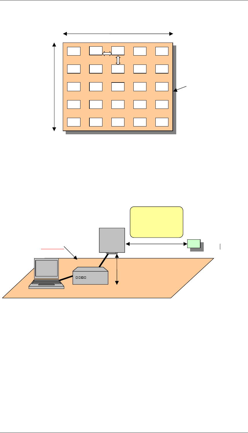
7.2 Multiple-tag Setup
The multiple-tag setup may be a flat surface of a non-conducting material with maximum area
of 1 m x 1 m. The multiple-tag setup contains a group of tags from the same (homogeneous) or
different (mixed) label or inlay manufacturers. This tags shall contain a class 1 Gen 2 IC. The
tags shall be evenly distributed and maintain a separation between them of not less than 10 cm.
The maximum number of tags in the setup shall be 25. Figure 6 depicts the multiple-tag setup.
Date: 2006-08-04 Version 1.2.4 Page 34 of 84
Interoperability Test System for EPC compliant Class-1 Gen-2 UHF RFID
3
3
3
3
3
3
3
3
3
3
g
Non
-
conductin
surface
3
3
3
3
3
3
3
3
3
3
3
3
3
10 cm
3
3
1 m
1 m
Figure 1. Multi-tag Board
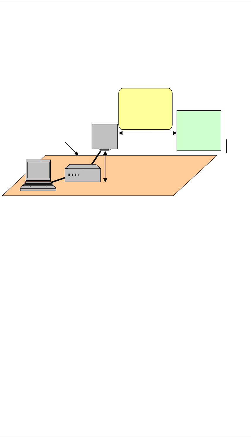
7.3 Test Sites for Interoperability
Test Site
3
Height of the
antenna
4
1
2
Suitable distance
between the
interrogator and
the tag
Flat
surface
1 Interrogator antenna
2 Interrogator
3 Tag
4 Host
Figure 2. Test Site 1
Description of the tag placement:
- The tag shall be at fixed and stationary position.
Date: 2006-08-04 Version 1.2.4 Page 35 of 84
Interoperability Test System for EPC compliant Class-1 Gen-2 UHF RFID
- The geometrical centre of the tag shall be aligned horizontally with the
geometrical centre of the interrogator antenna and the tag orientation facing the
antenna.
- Tag placement shall be on a non-conducting material, for example cardboard.
Tags should be placed facing the interrogator antenna.
Test Sites 2 and 3
Height of the
antenna
4
1
2
3
Flat surface
Suitable distance
between the
interrogator and
-
tag
the multiple
setup
1 Interrogator antenna
2 Interrogator
3 Multiple-tag setup
4 Host
Figure 3. Test Sites 2 and 3
Description:
- The multiple-tag setup shall be at fixed and stationary position.
- The geometrical center of the multiple-tag setup shall be aligned horizontally with the
geometrical center of the interrogator antenna and its orientation facing the antenna.
- Test Site 2 shall consist of a population of tags from the same vendor. This is referred
to as a homogeneous multi-tag population.
- Test Site 3 shall consist of a population of tags from the different vendors. This is
referred to as a mixed multi-tag population.
Date: 2006-08-04 Version 1.2.4 Page 36 of 84

Interoperability Test System for EPC compliant Class-1 Gen-2 UHF RFID
Date: 2006-08-04 Version 1.2.4 Page 37 of 84
7.4 Qualified Equipment
In order to conduct interoperability tests a set of QE must be identified to used. QEs are
standard commercial products that have been selected for the purpose of interoperability testing
and shown to be fully compliant with reference standards.
When implementing the test cases the test operator can choose between two possible test
scenarios:
- Interrogator under test against tag under test. There is not qualified equipment in this
test scenario. Both, the interrogator and the tag are EUTs.
- EUT tested against qualified equipment. The qualified equipment will be an
interrogator, a tag or a multiple-tag set-up depending on the device submitted for
testing and the test purpose.
See Annex D for more information.
7.5 Test System Validation
The system validation will be carried out using an interrogator and a tag population with the
following characteristics:
- The selected interrogator and the tag population shall belong to the same
manufacturer, in order to assure proper communication between them.
- Both the interrogator and tag population shall have successfully passed the RF and
Protocol conformance tests.
Each interoperability test case will be validated running it with the described devices and until a
complete test campaign is completed. This can be accomplished by single stepping through each
test case or by exercising a group of Script Files that accomplish the same task.

INTEROP-RFID IS PROFORMA RFID INTEROP TEST SYSTEM ANNEX A
ANNEX A
IS and IXIT specification
A.1 Scope
The present document provides the Implementation Statement (IS) proforma for the radio-
frequency identification (RFID) system operating in the 860 MHz – 960 MHz frequency range
defined in EPCglobal Class-1 Generation-2 UHF RFID Protocol V.1.0.9 in compliance with the
relevant requirements, and in accordance with the relevant guidance given in ISO/IEC9646.
A.2 References
[1] EPCglobal Class-1 Generation-2 UHF RFID Protocol V.1.0.9
[2] ISO/IEC 9646-1: "Information technology - Open systems interconnection -
Conformance testing methodology and framework – Part 1: General concepts".
[3] ISO/IEC 9646-7: "Information technology - Open systems interconnection -
Conformance testing methodology and framework – Part 7: Implementation
Conformance Statements".
[4] ETSI TS 102 237-1 v 4.1.1 (2003-12): Telecommunications and Internet Protocol
Harmonization Over Networks (TIPHON) Release 4; Interoperability test methods
and approaches; Part 1: Generic approach to interoperability testing.
A.3 Definitions
In particular, the following terms and definitions apply:
Interoperability Statement (IS): It is a checklist of the capabilities/functionalities supported
by the Equipment Under Test. IS is used to select and parameterize test cases and as an indicator
for basic interoperability between different products.
IS proforma: A document, in the form of a questionnaire, which when completed for an
implementation or system becomes an IS.
Implementation eXtra Information for Testing (IXIT): It contains additional information
(e.g., specific addresses, timer values, etc.) necessary for testing.
A.4 Abbreviations
IS Implementation Statement
IUT Implementation Under Test
SUT System Under Test
A.5 Conformance to this IS proforma specification
If it claims to conform to the present document, the actual IS proforma to be filled in by a
supplier shall be technically equivalent to the text of the IS proforma given in annex A, and
shall preserve the numbering/naming and ordering of the proforma items.
An IS which conforms to the present document shall be a conforming IS proforma completed in
accordance with the guidance for completion given in clause 1.1.
Date: 2006-08-04 Version 1.2.4 Page 38 of 84

INTEROP-RFID IS PROFORMA RFID INTEROP TEST SYSTEM ANNEX A
IS proforma for EPCglobal Class-1 Generation-2 UHF RFID Protocol
V.1.0.9. Interoperability Test Cases.
A.6 Guidance for completing the IS proforma
A.6.1 Purposes and structure
The purpose of this IS proforma is to provide a mechanism whereby a supplier of an
implementation of the requirements defined in the specification “EPCglobal Class-1
Generation-2 UHF RFID Protocol” may provide information about the implementation in a
standardized manner.
The IS proforma is subdivided into clauses for the following categories of information:
- Guidance for completing the IS proforma;
- Identification of the implementation;
- Identification of the <reference specification type>;
- Global statement of conformance;
- Instructions for completing the IS proforma;
- Identification of the implementation;
- Identification of the protocol;
- Global statement of conformance;
- Roles;
- Major capabilities;
- Timers
- Extra information for testing
A.6.2 Abbreviations and conventions
Item column
The item column contains a number which identifies the item in the table.
Item description column
The item description column describes in free text each respective item (e.g. parameters, timers,
etc.). It implicitly means "is <item description> supported by the implementation?".
Document reference column
The document reference column makes reference to EPCglobal Class-1 Generation-2 UHF
RFID Protocol V.1.0.9 except where explicitly stated otherwise.
IS reference column
The IS reference contains the identifier of a particular item. It is used in the selection criteria of
each test purpose.
Date: 2006-08-04 Version 1.2.4 Page 39 of 84

INTEROP-RFID IS PROFORMA RFID INTEROP TEST SYSTEM ANNEX A
Status column
The following notations, defined in ISO/IEC 9646-7, are used for the status column:
m mandatory - the capability is required to be supported.
o optional - the capability may be supported or not.
n/a not applicable - in the given context, it is impossible to use the capability.
x prohibited (excluded) - there is a requirement not to use this capability in the given
context.
o.i qualified optional - for mutually exclusive or selectable options from a set. "i" is an
integer which identifies an unique group of related optional items and the logic of
their selection which is defined immediately following the table.
Support column
The support column shall be filled in by the supplier of the implementation. The following
common notations, defined in ISO/IEC 9646-7, are used for the support column:
Y or y supported by the implementation.
N or n not supported by the implementation.
N/A, n/a or - no answer required (allowed only if the status is n/a, directly or after evaluation of a
conditional status).
Values allowed column
The values allowed column contains the type, the list, the range, or the length of values allowed.
The following notations are used:
- range of values: <min value> .. <max value>
example: 5 .. 20
Values supported column
The values supported column shall be filled in by the supplier of the implementation. In this
column, the values or the ranges of values supported by the implementation shall be indicated.
A.6.3 Instructions for completing the IS proforma
The supplier of the implementation shall complete the IS proforma in each of the spaces
provided. In particular, an explicit answer shall be entered, in each of the support or supported
column boxes provided, using the notation described in clause
If necessary, the supplier may provide additional comments in space at the bottom of the tables
or separately.
More detailed instructions are given at the beginning of the different clauses of the IS proforma.
A.6.4 Identification of the implementation
Identification of the Implementation Under Test (IUT) and the system in which it resides (the
System Under Test (SUT)) should be filled in so as to provide as much detail as possible
regarding version numbers and configuration options.
The product supplier information and client information should both be filled in if they are
different.
A person who can answer queries regarding information supplied in the IS should be named as
the contact person.
Date: 2006-08-04 Version 1.2.4 Page 40 of 84

INTEROP-RFID IS PROFORMA RFID INTEROP TEST SYSTEM ANNEX A
Date of the statement
.........................................................................................................................................................................
Implementation Under Test (IUT) identification
IUT name:
.........................................................................................................................................................................
.........................................................................................................................................................................
IUT version:
.........................................................................................................................................................................
System Under Test (SUT) identification
SUT name:
.........................................................................................................................................................................
.........................................................................................................................................................................
Hardware configuration:
.........................................................................................................................................................................
.........................................................................................................................................................................
.........................................................................................................................................................................
Operating system:
.........................................................................................................................................................................
Product supplier
Name:
.........................................................................................................................................................................
Address:
.........................................................................................................................................................................
.........................................................................................................................................................................
.........................................................................................................................................................................
Telephone number:
.........................................................................................................................................................................
Facsimile number:
.........................................................................................................................................................................
E-mail address:
.........................................................................................................................................................................
Additional information:
.........................................................................................................................................................................
.........................................................................................................................................................................
.........................................................................................................................................................................
Client (if different from product supplier)
Name:
.........................................................................................................................................................................
Address:
.........................................................................................................................................................................
.........................................................................................................................................................................
.........................................................................................................................................................................
Telephone number:
.........................................................................................................................................................................
Facsimile number:
.........................................................................................................................................................................
E-mail address:
.........................................................................................................................................................................
Additional information:
.........................................................................................................................................................................
.........................................................................................................................................................................
IS contact person
(A person to contact if there are any queries concerning the content of the IS)
Name:
.........................................................................................................................................................................
Date: 2006-08-04 Version 1.2.4 Page 41 of 84

INTEROP-RFID IS PROFORMA RFID INTEROP TEST SYSTEM ANNEX A
Telephone number:
.........................................................................................................................................................................
Facsimile number:
.........................................................................................................................................................................
E-mail address:
.........................................................................................................................................................................
Additional information:
.........................................................................................................................................................................
.........................................................................................................................................................................
.........................................................................................................................................................................
Identification of the specification
This IS proforma applies to the Interoperability test cases of the following standard: EPCglobal
Class-1 Generation-2 UHF RFID Protocol V.1.0.9
Global statement of conformance
Are all mandatory capabilities implemented? (Yes/No) ...................
NOTE: Answering "No" to this question indicates non-conformance to the specification.
Non-supported mandatory capabilities are to be identified in the IS, with an explanation of
why the implementation is non-conforming, on pages attached to the IS proforma.
A.6.5. Roles
Item Role
Document
Reference
IS Reference Status Support
1
Interrogator 2.2.1 A:1.1/1 o.1
2
Tag 2.2.2 A:1.1/2 o.1
Table A.1. Roles
o.1 - It is mandatory to support exactly one of these items.
Comments:
Interrogator Role
Item Operation
Document
Reference
IS
Reference
Status Support
1
Select 6.3.2.6 A:1.2/1 m
2
Inventory 6.3.2.6 A:1.2/2 m
3
Access 6.3.2.6 A:1.2/3 m
4
Interrogators supports 4
sessions (denoted S0, S1, S2,
S3)
6.3.2.2 A:1.2/4 m
Table A.2. Basic operations and capabilities for managing tag populations
Comments:
Date: 2006-08-04 Version 1.2.4 Page 42 of 84

INTEROP-RFID IS PROFORMA RFID INTEROP TEST SYSTEM ANNEX A
Item Command
Document
Reference
IS Reference Status Support
1
Select 6.3.2.10.1.1
A:1.3/1
m
2
Query 6.3.2.10.2.1
A:1.3/2
m
3
QueryAdjust 6.3.2.10.2.2
A:1.3/3
m
4
QueryRep 6.3.2.10.2.3
A:1.3/4
m
5
ACK 6.3.2.10.2.4
A:1.3/5
m
6
NAK 6.3.2.10.2.5
A:1.3/6
m
7
Req_RN 6.3.2.10.3.1
A:1.3/7
m
8
Read 6.3.2.10.3.2
A:1.3/8
m
9
Write 6.3.2.10.3.3
A:1.3/9
m
10
Kill 6.3.2.10.3.4
A:1.3/10
m
11
Lock 6.3.2.10.3.5
A:1.3/11
m
12
Access 6.3.2.10.3.6
A:1.3/12
o
13
BlockWrite 6.3.2.10.3.7
A:1.3/13
o
14
BlockErase 6.3.2.10.3.8
A:1.3/14
o
Table A.3. Commands supported
Comments:
Date: 2006-08-04 Version 1.2.4 Page 43 of 84

INTEROP-RFID IS PROFORMA RFID INTEROP TEST SYSTEM ANNEX A
Tag Role
Item Memory bank
Document
Reference
IS Reference Status Support
1
Reserved memory 6.3.2.1
A:1.4/1
m
2
EPC memory 6.3.2.1
A:1.4/2
m
3
TID memory 6.3.2.1
A:1.4/3
m
4
User memory 6.3.2.1
A:1.4/4
o
Table A.4. Memory banks supported
Comments:
Item Password
Document
Reference
IS Reference Status Support
1
Kill password 6.3.2.1.1
A:1.5/1
o
2
Access password 6.3.2.1.2
A:1.5/2
o
Table A.5. Stored passwords in Reserved memory bank
Comments:
Item EPC Data
Document
Reference
IS Reference
Status Support
1
CRC-16 6.3.2.1
A:1.6/1
m
2
PC (Protocol control) 6.3.2.1
A:1.6/2
m
3
Object identifier code 6.3.2.1
A:1.6/3
m
Table A.6. Stored data in EPC memory bank
Comments:
Item Object identifier
Document
Reference
IS Reference
Status Support
1
EPC (EPCglobal members) 6.3.2.1
A:1.7/1
o.1
2
Other object identifier code 6.3.2.1
A:1.7/2
o.1
Table A.7. Object identifier type
o.1: It is mandatory to support one of these items.
Comments:
Date: 2006-08-04 Version 1.2.4 Page 44 of 84

INTEROP-RFID IS PROFORMA RFID INTEROP TEST SYSTEM ANNEX A
Item TID Data
Document
Reference
IS
Reference
Status Support
1
8-
b
it ISO/IEC 15963 allocation class
identifier
6.3.2.1
A:1.8/1
m
2
12-bit tag mask-designer identifier 6.3.2.1
A:1.8/2
c.1
3
12-bit tag model number 6.3.2.1
A:1.8/3
c.1
Table A.8. Stored data in TID memory bank
c.1: Mandatory for EPCglobal members (A:3.1.3.2/1 in Table 1.7)
Comments:
Item States
Document
Reference
IS
Reference
Status Support
1
Ready state 6.3.2.10.1.1
A:1.9/1
m
2
Arbitrate state 6.3.2.10.2.1
A:1.9/2
m
3
Reply state 6.3.2.10.2.2
A:1.9/3
m
4
Acknowledged state 6.3.2.10.2.3
A:1.9/4
m
5
Open state 6.3.2.10.2.4
A:1.9/5
m
6
Secured state 6.3.2.10.2.5
A:1.9/6
m
7
Killed state 6.3.2.10.3.1
A:1.9/7
m
Table A.9. States
Comments:
Date: 2006-08-04 Version 1.2.4 Page 45 of 84

INTEROP-RFID IS PROFORMA RFID INTEROP TEST SYSTEM ANNEX A
Item Command
Document
Reference
IS
Reference
Status Support
1
Select 6.3.2.10.1.1
A:1.10/1
m
2
Query 6.3.2.10.2.1
A:1.10/2
m
3
QueryAdjust 6.3.2.10.2.2
A:1.10/3
m
4
QueryRep 6.3.2.10.2.3
A:1.10/4
m
5
ACK 6.3.2.10.2.4
A:1.10/5
m
6
NAK 6.3.2.10.2.5
A:1.10/6
m
7
Req_RN 6.3.2.10.3.1
A:1.10/7
m
8
Read 6.3.2.10.3.2
A:1.10/8
m
9
Write 6.3.2.10.3.3
A:1.10/9
m
10
Kill 6.3.2.10.3.4
A:1.10/10
m
11
Lock 6.3.2.10.3.5
A:1.10/11
m
12
Access 6.3.2.10.3.6
A:1.10/12
o
13
BlockWrite 6.3.2.10.3.7
A:1.10/13
o
14
BlockErase 6.3.2.10.3.8
A:1.10/14
o
Table A.10. Commands supported
Comments:
Values
Item MemBank
Document
Reference
IS
Reference
Status Support
Allowed Supported
1
Reserved memory bank 6.3.2.1 B.1.11/1 m 00
2
EPC memory bank 6.3.2.1
B.1.11/2
m 01
3
TID memory bank 6.3.2.1
B.1.11/3
m 10
4
User memory bank 6.3.2.1
B.1.11/4
m 11
Table A.11. Logical partitioning of the memory banks
Comments:
Date: 2006-08-04 Version 1.2.4 Page 46 of 84

INTEROP-RFID IS PROFORMA RFID INTEROP TEST SYSTEM ANNEX A
Values
Item Data
Document
Reference
IS
Reference
Status Support
Allowed Supported
1
Kill password in Reserved memory 6.3.2.1 B.1.12/1 c.1 00
h
- 1F
h
2
Access password in Reserved
memory
6.3.2.1 B.1.12/2 c.2 20
h
- 3F
h
3
CRC-16 in EPC memory
6.3.2.1 B.1.12/3 m 00
h
– 0F
h
4
Protocol Control (PC) in EPC
memory
6.3.2.1
B.1.12/4 m 10
h
– 1F
h
5
Object identifier code in EPC
memory
6.3.2.1 B.1.12/5 m Above 1F
h
6
ISO/IEC 15963 allocation class
identifier in TID memory
6.3.2.1 B.1.12/6 m 00
h
- 07
h
7
Other identifier information in TID
memory
6.3.2.1 B.1.12/7 m Above 07
h
8
Tag mask-designer identifier in TID
memory
6.3.2.1 B.1.12/8 c.3 08
h
– 13
h
9
Tag model number in TID memory
6.3.2.1 B.1.12/9 c.3 14
h
– 1F
h
Table A.12. Memory locations of stored data in each memory bank
c.1: Mandatory for tags that implement the kill password (
A:3.1.2/1 in Table 1.5)
c.2: Mandatory for tags that implement the access password (
A:3.1.2/2 in Table 1.5)
c.3: Mandatory for EPCglobal members (
A:3.1.3.2/1 in Table 1.7)
Comments:
Date: 2006-08-04 Version 1.2.4 Page 47 of 84

INTEROP-RFID IS PROFORMA RFID INTEROP TEST SYSTEM ANNEX A
Date: 2006-08-04 Version 1.2.4 Page 48 of 84
IXIT proforma for EPCglobal Class-1 Generation-2 UHF RFID
Protocol V.1.0.9. Interoperability Test Cases.
A.7 Operating Parameters
Is the prototype controlled by means of an external PC or terminal unit?
(Yes/No)
Does the prototype notify (e.g. by means of messages) if the operation
has been executed correctly?
(Yes/No)
Main power characteristics:
(AC/DC)
Supply voltage:___________________________________________________ _____
Supply current:_______________________________________________ _________
Operating frequency range:______________________________________________
Implemented modulation format in Interrogator-to-Tag communication:____________
Implemented modulation format in Tag-to-Interrogator communication:____________
Implemented codification format in Tag-to-Interrogator communication:____________
Frequency sub-band:____________________________________________________
Number of channels:__________________________________________ __________
Channel width:_________________________________________________________
Interoperability test mode description:

INTEROP TEST REPORT ANNEX B
ANNEX B
Test Report
Report No.: #report number#
TEST NAME: #test name#
Product Name
: #product name#
Trade Mark
: #trade mark#
Product ID
: IUT_PRODUCT_ID
Manufacturer
: MANUFAC_COMPANY
Client
: CLIENT_COMPANY
Standard(s)
: EPCglobal Class-1 Generation-2 UHF Protocol V1.0.9
This test report includes 4 annexes and therefore the total number of pages of this test report is x.
This report shall not be reproduced except in full without the written permission of the Test
Laboratory and shall not be quoted out of context.
Date: 2006-06-27 Version 1.2 Page 49 of 84

IDENTIFICATION SUMMARY
B.1 Test Laboratory
Name:
Address
City:
Postal code:
Country:
Telephone:
Fax:
URL:
Contact person:
Name:
e-mail:
Competences and guarantees:
MET Laboratories Inc. is a testing laboratory competent to carry out the tests described in this
report.
In order to assure the traceability to other national and international laboratories, MET
Laboratories has a calibration and maintenance programme for its measuring equipment.
MET Laboratories guarantees the reliability of the data presented in this report, which is the result
of measurements and tests performed to the item under test on the date and under the conditions
stated on the report and is based on the knowledge and technical facilities available at MET
Laboratories at the time of execution of the test.
MET Laboratories is liable to the client for the maintenance by its personnel of the confidentiality
of all information related to the item under test and the results of the test.
Date: 2006-06-27 Version 1.2 Page 50 of 84

INTEROP TEST REPORT ANNEX B
B.2 Client
NAME:
V.A.T. :
Address:
City:
Postal code:
Country:
Telephone:
Contact person:
Name:
e-mail:
B.3 Manufacturer
NAME:
V.A.T. :
Address:
City:
Postal code:
Country:
Telephone:
Contact person:
Name:
e-mail:
Date: 2006-06-27 Version 1.2 Page 51 of 84

INTEROP TEST REPORT ANNEX B
B.4 Implementation Under Test
PRODUCT NAME:
Trademark:
Product ID:
Hw version:
Sw version:
Profiles supported:
Protocol Specification(s):
IS:
SEE ANNEX A
Description of IUT 1:
Sample method:
Samples undergoing test have been selected by: The
Client
B.5 Implementation Under Test 2
PRODUCT NAME:
Trademark:
Product ID:
Hw version:
Sw version:
Profiles supported:
Protocol Specification(s):
IS:
SEE ANNEX A
Description of IUT 2:
Sample method:
Samples undergoing test have been selected by: The
Client
Date: 2006-06-27 Version 1.2 Page 52 of 84

INTEROP TEST REPORT ANNEX B
B.6 Testing Environment
IXIT:
SEE ANNEX B
Period of testing:
Conformance log reference:
SEE ANNEX C
Retention date for log reference:
5 years
Test Requested
Interoperability testing for #IUT#.
B.7 Means of testing identification:
Hardware:
RIDER INTEROP TESTER (HW SEE XX)
Software:
RIDER INTEROP TESTER (SW see xx)
Test Setup:
Test Procedures:
B.8 Test conditions:
NOMINAL
TEMPERATURE IN THE RANGE 18ºC TO 27 ºC
EXTREME
MAX NOMINAL MIN
TEMPERATURE
VOLTAGE
Date: 2006-06-27 Version 1.2 Page 53 of 84
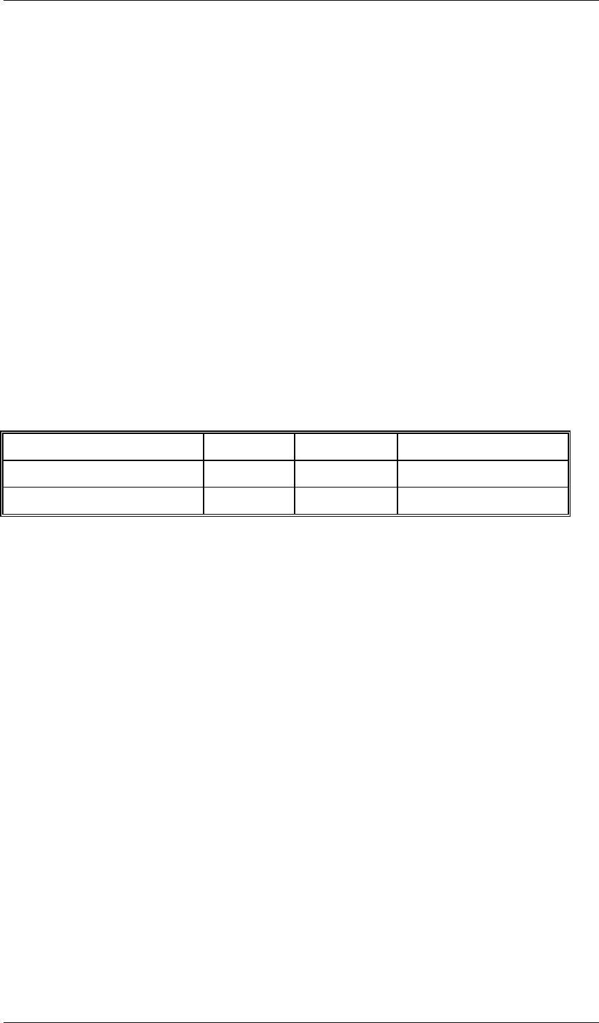
INTEROP TEST REPORT ANNEX B
B.9 Limits and reservations
The test results presented in this test report apply only to the implementations under test (IUT 1
& IUT 2) declared in section 1.4 of this report, for the functionality described in the relevant
Implementation Statement (IS), as presented for test on the date(s) declared in section 1.5 and
configured as declared in the relevant Implementation eXtra Information for Testing (IXIT).
This test report does not constitute or imply, by its own, to be an approval of the product by
Qualification Bodies, Certification Bodies or competent Authorities.
This document is only valid if complete; no partial reproduction can be made without written
approval of the Test Laboratory.
This test report cannot be used partially or in full for publicity and/or promotional purposes
without previous written approval of the Test Laboratory.
B.10 Record of agreement
The following samples were used for testing.
INTERNAL CONTROL NO.: ELEMENT: SERIAL NO.: DATE OF RECEPTION:
xxxxx/13
xxxxx/05
Date: 2006-06-27 Version 1.2 Page 54 of 84

INTEROP TEST REPORT ANNEX B
B.11 Iut Conformance Status
These IUT 1 & IUT 2 have #NOT# been shown by conformance assesment to be non-
conforming to the referenced specification(s).
STATIC CONFORMACE ERRORS?
Dynamic Conformance errors?
Number of test cases run
PASSED:
Failed:
Inconclusive:
Total:
B.12 Static Conformance Summary
The IS(s) for IUT 1 & IUT 2 is #NOT# consistent with the static conformance requirements in
the referenced base specification(s).
The qualified IS/IXIT menu of the test system was defined in accordance with the client.
B.13 Dynamic Conformance Summary
The test campaign did #NOT# reveal errors in IUT 1 & IUT 2.
B.14 Static Conformance Review Report
IS CORRECT
IS INCORRECT
IS NOT FILLED
Date: 2006-06-27 Version 1.2 Page 55 of 84

INTEROP TEST REPORT ANNEX B
Date: 2006-06-27 Version 1.2 Page 56 of 84
B.15 Test Campaign Report
The abbreviations used in the header row of the test campaign report tables are:
Applicable: Indicates whether or not a test case has been selected for execution against
IUTs identified in section 1.4 according to the analysis of the information in
the IS and IXIT for IUT 1 & IUT 2.
Run: Indicate whether or not the corresponding test case has been run to
completion.
Verdict: Records the verdict assigned to each test case run to completion. Following
verdicts are possible:
Pass: If the test case passed
Fail: If the test case failed
Inc: If the test case is inconclusive.
Observations: Provides a reference to additional information relevant to the test presented
in section 7.
Test Case Id Role Applicable Run Verdict Observations
B.16 Observations

INTEROP Interoperability Tests for Printers ANNEX C
ANNEX C
Interoperability Tests for Printers
C.1 Manufacturer Data
Printer manufacturers integrate OEM interrogators into there various printers designs.
Printer designs are diverse and consequently, interrogator performance in any given printer
design is very carefully tuned by the printer manufacturer to yield optimal performance within
that environment.
For optimal RFID supply performance the printer user is to carefully follow all of the
manufactures recommendation regarding printer supply selection, and operation. This may
require that only the printer manufacturers approved RFID label and tag supplies be used in a
particular model of printer.
The basic function of the printer interrogator is to correctly program a previously blank tag with
input data.
To perform this function the interrogator may use a sequence of internal commands to erase,
verify and write to the transponder.
A read write operation must be directed only at the transponder that is intended for that
operation. It is required that the transponder being programmed is correctly identified so as not
to inadvertently program adjacent transponders (Adjacency control).
Tests of interoperability for the printer are defined as the ability of the printer interrogator to
perform specified read write operations as defined in this document and more importantly for all
RF transponders programmed by the printer to be read by any EPCglobal certified reader. The
only exception is for transponders identified by the printer Interrogator as being unusable.
Unusable transponders are to be identified as defective.
Date: 2006-06-27 Version 1.2 Page 57 of 84

INTEROP Interoperability Tests for Printers ANNEX C
C.2 Manufacturer Identification
Supplier
Contact point for queries samples
Product Name(s) and Version(s) (NOTE)1
Other information necessary for full inter op
testing - e.g., mounting information; are
parameters in table 2.1 in free air or mounted to
material
PC controller
NOTE 1 The terms Name and Version should be interpreted appropriately to correspond with a
supplier’s terminology (e.g. Type, Series, Model).
REF Feature Capability Min Typical Max Units
EPCglobal™ Certified Interrogator
Module
North American regulatory compliance
European regulatory compliance
Operating frequency
MHz
Operating temperature
ºC
Storage temperature
ºC
Operating humidity
%
Supported EPCglobal Protocols
Class 1 Generation 2 (C1G2)
Table C.1 Manufacturer product summary
Notes: NC = Non-Condensing
Date: 2006-06-27 Version 1.2 Page 58 of 84

INTEROP Interoperability Tests for Printers ANNEX C
C.3 Reference from EPCglobal Gen 2 Specification
Reference to ISO/IEC Document 18000-6C Information technology – Radio frequency
identification for item management- Part 6C Parameters for air interface communications at 860
MHz to 960MHz
Table 39 – Lock Action-field functionality
Date: 2006-06-27 Version 1.2 Page 59 of 84

INTEROP Interoperability Tests for Printers ANNEX C
C.4 Test Suit Structure
Write + Identify Failed
Write + pwdlock
Write + pwdlock + permalock
Write + No Lock
One
Tag
Write
Write Write + Permalock
EPC EPC
A
ccess
A
ccess
*Kill
Proven on Exterenal
*Kill
Proven on Exterenal
User
Reader
User
Reader
TID TID
Write + Pwd Lock Write +Pwd Lock+ Permalock
EPC EPC
A
ccess
A
ccess
*Kill
Proven on Exterenal
*Kill
Proven on Exterenal
User
Reader
User
Reader
TID TID
*
Test condition that does not apply to printer operation.
User & TID functions not yet implemented in available Gen 2 product
Special Tests
1. Read Tag - Ability to read and recognize EPC capable tag.
2. Seralized Batch - Ability to print 10 EPC tags with sequntial numbering.
3. Identify Failed - Ability to identify inoperative transponder.
Date: 2006-06-27 Version 1.2 Page 60 of 84

INTEROP Interoperability Tests for Printers ANNEX C
#n. TC Id. Test Purpose
#1
TP/WR/ONE/BAS/BV-01
The printer is able to write data to the
EPC field.
#2
TP/WR/ONE/BAS/BV-02
The printer is able to write data to the
Access password field
#3
TP/WR/ONE/BAS/BV-03
The printer is able to write data to the
Kill password field.
#4
TP/WR/ONE/IDE/BV-01
The printer is able to identify inoperative
transponders before writing.
#5
TP/WR/ONE/PWD/BV-01
The printer is able to write data to EPC
and Access password fields locking both
with pwdlock.
#6
TP/WR/ONE/PWD/BV-02
The printer is able to write data to Kill
and Access password fields locking both
with pwdlock.
Table C.2 Test Cases List Reference
Date: 2006-06-27 Version 1.2 Page 61 of 84

INTEROP Interoperability Tests for Printers ANNEX C
C.5 TP Naming Convention
Identifier: TP/<main functionality>/<tag scenario>/<functionality subgroup>/<type>-<nn>
<main functionality> WR (Write)
<tag scenario> ONE (One Tag)
<functionality subgroup> BAS (Basic = No Lock)
IDE (Identify Failed)
PWD (pwdlock)
PPL (pwdlock +permalock)
<type> BV (Valid Behaviour)
BI (Invalid Behaviour)
<nn> sequential number (01-99)
Valid Behaviour (BV) tests: This subgroup provides testing to verify that the EUT
reacts in conformity with the specified functionality.
Invalid Behaviour (BI) tests: This subgroup provides testing to verify that the EUT
reacts in conformity with the specified functionality, after receipt of a syntactically,
semantically or functionality invalid event.
Date: 2006-06-27 Version 1.2 Page 62 of 84
INTEROP Interoperability Tests for Printers ANNEX C
C.6 Test Case Procedures
WRITE with NO LOCK
TP Id: TP/WR/ONE/BAS/BV-01
Version 0.3
Selected: Yes
No
Test Purpose: Show that the printer is able to write data to the EPC field.
Verdict
Step Test description
Pass Fail
1 Thread the label roll and set up the printer to be ready for operation.
2
Act on the printer to write data with NO lock to the EPC field. Length
of the data shall be the same as the size of the memory bank.
3
Fill the gap (in hexadecimal) with the written data to the EPC field.
____________________________________________________
4
Verification of the test case:
Verify the Write with No lock operation by reading the EPC memory
bank with an external interrogator.
5
Fill the gap (in hexadecimal) with the tag data reported by the first
external interrogator.
Does the reported data match the previous written data in the EPC field?
Yes No
Observations:
External interrogators used for the verification:
Success
criteria:
The read data by each external interrogator shall match the written data by the printer.
DATE PRINTER
TAG
Date: 2006-06-27 Version 1.2 Page 63 of 84
INTEROP Interoperability Tests for Printers ANNEX C
WRITE with NO LOCK
TP Id: TP/WR/ONE/BAS/BV-02
Version 0.3
Selected: Yes
No
Test Purpose: Show that the printer is able to write data to the Access password field.
Verdict
Step Test description
Pass Fail
1 Thread the label roll and set up the printer to be ready for operation.
2
Act on the printer to write data with NO lock to the Access password
field. Length of the data shall be the same as the size of the Access
password field.
3
Fill the gap (in hexadecimal) with the written data to the Access field.
____________________________________________________
4
Verification of the test case:
Verify the Write with No lock operation by reading the Access
password with an external interrogator.
5
Fill the gap (in hexadecimal) with the tag data reported by the first
external interrogator.
Does the reported data match the previous written data in the Access
field?
Yes No
Observations:
External interrogators used for the verification:
Success
criteria:
The read data by each external interrogator shall match the written data by the printer.
DATE PRINTER
TAG
Date: 2006-06-27 Version 1.2 Page 64 of 84

INTEROP Interoperability Tests for Printers ANNEX C
WRITE with NO LOCK
TP Id: TP/WR/ONE/BAS/BV-03
Version 0.3
Selected: Yes
No
Test Purpose: Show that the printer is able to write data to the Kill password field.
Verdict
Step Test description
Pass Fail
1 Thread the label roll and set up the printer to be ready for operation.
2
Act on the printer to write data with NO lock to the Kill password
field. Length of the data shall be the same as the size of the Kill
password field.
3
Fill the gap (in hexadecimal) with the written data to the Kill password
field.
____________________________________________________
4
Verification of the test case:
Verify the Write with No lock operation by reading the Kill password
with an external interrogator.
5
Fill the gap (in hexadecimal) with the tag data reported by the first
external interrogator.
Does the reported data match the previous written data in the Kill
password field?
Yes No
Observations:
External interrogators used for the verification:
Success
criteria:
The read data by each external interrogator shall match the written data by the printer.
DATE PRINTER
TAG
Date: 2006-06-27 Version 1.2 Page 65 of 84
INTEROP Interoperability Tests for Printers ANNEX C
WRITE + IDENTIFY FAILED
TP Id: TP/WR/ONE/IDE/BV-01
Version 0.3
Selected: Yes
No
Test Purpose: Show that the printer is able to identify inoperative transponders before writing.
Verdict
Step Test description
Pass Fail
1
Thread the label roll and set up the printer to be ready for operation. At
least, five inoperative transponders shall be in the label roll.
2
Act on the printer to write data with NO lock to any tag memory field.
Length of the data shall be the same as the size of the selected memory
field.
3
Continue writing labels until at least five inoperative transponders have
passed through the printer.
4 Has the printer identified as unusable all inoperative transponders? Yes No
Observations:
Success
criteria:
All unusable transponders are to be identified as defective by the printer.
DATE PRINTER
TAG
Date: 2006-06-27 Version 1.2 Page 66 of 84

INTEROP Interoperability Tests for Printers ANNEX C
WRITE with PWDLOCK
TP Id: TP/WR/ONE/PWD/BV-01
Version 0.3
Selected: Yes
No
Test Purpose: Show that the printer is able to write data to the EPC and Access password fields
locking both with pwdlock.
Verdict
Step Test description
Pass Fail
1 Thread the label roll and set up the printer to be ready for operation.
2
Act on the printer to write data with pwdlock to the EPC and Access
password fields. Length of the data shall be the same as the size of the
memory for each field.
3
Fill the gap (in hexadecimal) with the written data to the EPC field.
____________________________________________________
4
Fill the gap (in hexadecimal) with the written data to the Access field.
____________________________________________________
5
Verification of the test case:
Verify the Write with pwdlock operation by attempting to write the
EPC field with an external interrogator. In a subsequent read operation, it
is checked if a new EPC number has been programmed.
6
Arrange the external interrogator to write a different EPC number from
the EPC number specified in step 3.
7
Perform a read operation over the EPC field using the external
interrogator.
8
Fill the gap (in hexadecimal) with the tag data reported by the external
interrogator.
Does the reported data match the previous written data in the EPC field?
Yes No
9
Arrange the external interrogator to send an Access command followed
by a Write operation. The Access password used in the Access
command shall be the programmed value specified in step 4. The EPC
number to be written shall be different from the one specified in step 3.
10
Perform a read operation over the EPC field using the external
interrogator.
11
Fill the gap (in hexadecimal) with the tag data reported by the external
interrogator.
Does the reported data match the previous written data in the EPC field?
No Yes
Date: 2006-06-27 Version 1.2 Page 67 of 84

INTEROP Interoperability Tests for Printers ANNEX C
Observations:
External interrogators used for the verification:
Success
criteria:
In the verification, an error should be obtained as result of the first write operation. Thus
the read EPC data should match the programmed EPC by the printer. The second write
operation should be successful so a different EPC number should be programmed.
DATE PRINTER
TAG
Date: 2006-06-27 Version 1.2 Page 68 of 84

INTEROP Interoperability Tests for Printers ANNEX C
WRITE with PWDLOCK
TP Id: TP/WR/ONE/PWD/BV-02
Version 0.3
Selected: Yes
No
Test Purpose: Show that the printer is able to write data to the Kill and Access password fields locking
both with pwdlock.
Verdict
Step Test description
Pass Fail
1 Thread the label roll and set up the printer to be ready for operation.
2
Act on the printer to write data with pwdlock to the Kill and Access
password fields. Length of the data shall be the same as the size of the
memory for each field.
3
Fill the gap (in hexadecimal) with the written data to the Kill password
field.
____________________________________________________
4
Fill the gap (in hexadecimal) with the written data to the Access field.
____________________________________________________
5
Verification of the test case:
Verify the Write with pwdlock operation by attempting to write the Kill
password field with an external interrogator. In a subsequent read
operation, it is checked if a new Kill password has been programmed.
6
Arrange the external interrogator to write a different Kill password from
the data specified in step 3.
7
Perform a read operation over the Kill password field using the external
interrogator.
8
Fill the gap (in hexadecimal) with the tag data reported by the external
interrogator.
Does the reported data match the previous written data in the Kill
password field?
Yes No
9
Arrange the external interrogator to send an Access command followed
by a Write operation. The Access password used in the Access
command shall be the programmed value specified in step 4. The Kill
password to be written shall be different from the one specified in step 3.
10
Perform a read operation over the Kill password field using the external
interrogator.
11
Fill the gap (in hexadecimal) with the tag data reported by the external
interrogator.
Does the reported data match the previous written data in the Kill
password field?
No Yes
Date: 2006-06-27 Version 1.2 Page 69 of 84

INTEROP Interoperability Tests for Printers ANNEX C
Date: 2006-06-27 Version 1.2 Page 70 of 84
Observations:
External interrogators used for the verification:
Success
criteria:
In the verification, an error should be obtained as result of the first write operation. Thus
the read Kill data should match the programmed Kill password by the printer. The second
write operation should be successful so a different Kill password should be programmed.
DATE PRINTER
TAG
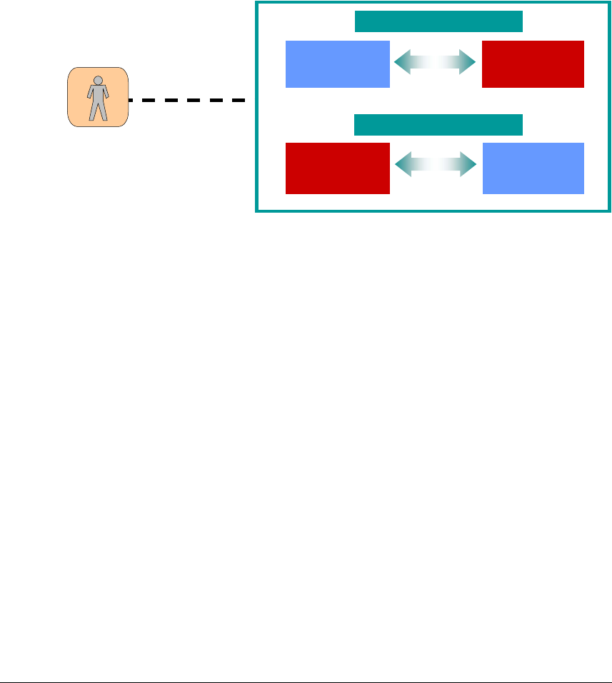
INTEROP Qualified Equipment Selection and Test Equipment ANNEX D
Annex D
Qualified Equipment Selection and Test
Equipment
D.1 Qualified Equipment
In order to ensure that interoperability tests are repeatable and consistent, a set of
products should be identified for use during interoperability testing – these products will
be called Qualified Equipment (QE). QEs are standard commercial products that have
been selected for the purpose of interoperability testing and shown to be fully compliant
with reference standards.
Test Operator
EUT
Interrogator
QE
Ta
g
S
y
stem Under Test 1
EUT
Tag
QE
Interrogator
S
y
stem Under Test 2
Test Scenario
Date: 2006-06-27 Version 1.2 Page 71 of 84

INTEROP Qualified Equipment Selection and Test Equipment ANNEX D
D.2 Definitions of Interoperability Testing Terms:
Interoperability testing: Activity of proving that end-to-end functionality between (at
least) two communicating systems is as required by the base standard(s) on which those
systems are based.
QE (Qualified Equipment): Grouping of one or more devices that has been shown, by
rigorous and well-defined testing, to interoperate with other equipment
SUT (System Under Test): It is a group of one or more devices that have not been
shown to interoperate with a previously Qualified Equipment.
System
Under Test
(SUT)
QE
1
QE
2
QE
n
...
Date: 2006-06-27 Version 1.2 Page 72 of 84

INTEROP Qualified Equipment Selection and Test Equipment ANNEX D
D.3 Selection of QE
1. EPCglobal sends a Request to invite manufacturers to submit products or
prototypes of both tags and interrogators to become QE.
2. A selection process takes place. The selection process involves:
a. Evaluation of the characteristics of the products, including
supported features.
b. Testing of interoperability within the set of submitted equipment.
c. Evaluation and Performance: Predictability of results and overall
performance.
d. Maximum representation of technologies and manufacturing
process.
e. Evaluation of usability and features to optimise testing such as
short read times and consistent measurement distances.
f. Life-time of product and maintenance.
3. The Test House will produce a report providing guidance and a recommendation
for selection of two or more QE of both tags and interrogators.
4. MET Labs will provide a list of potential QE to EPCglobal for ratification of the
selection. MET Labs nominates the equipment as Preliminary Qualified
Equipment (Pre-QE).
5. Pre-QE is used in the Hardware Certification Testing Program to run
interoperability testing.
6. If no problems are detected during operation and products successfully
compliance EPCglobal Gen-2 Conformance Testing, Pre-QE officially becomes
QE.
7. As the standard develops (changes, errata process, new features, etc.) the process
to select new QE is performed again.
D.4 Evaluation of the products
For Interrogators:
• The QE shall operate over all the declared frequency plans and sub-bands
specified in the EPCglobal Gen-2 Protocol.
• The QE shall support the maximum number of combinations of modulation and
codification formats, Tari/RTCal/TRCal values, etc.
• The QE shall implement a suitable combination of optional commands and
optional features.
• The QE will employ an intuitive GUI that allows test operators to run Test Cases
in customizable suites.
For Tags:
• The QE shall implement a suitable combination of optional commands, optional
features and optional memory banks and/or passwords to cover the most
significant implementations.
Date: 2006-06-27 Version 1.2 Page 73 of 84
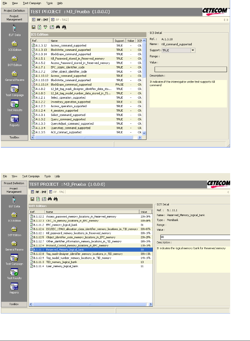
INTEROP Qualified Equipment Selection and Test Equipment ANNEX D
D.5 Test Equipment
2. All information supplied such as client data, manufacturer data and EUT general data
will be an input for the test system. IS and IXIT shall be filled prior to testing to
determine the test cases that apply for the EUT. The IS information will be checked for
consistency and in case of errors the test system will report the problems. (e.g., data
filled without using the appropriate format). Static Conformance Review and the
corresponding Test Case Mapping Table is derived from IS by the application. The
result is the set of test cases applicable to the EUT. They can be run individually or as a
batch using the scripting language.
Figure D.1. IS edition
Figure D.2. IXIT edition
Date: 2006-06-27 Version 1.2 Page 74 of 84

INTEROP Qualified Equipment Selection and Test Equipment ANNEX D
3. In the left hand side the window of icons show the different steps of the general
procedure for a test campaign.
Figure D.3. Test Campaign
The applicable test cases are executed progressively. It is also possible to specify some
items as number of executions, order of test cases execution and the values of the
parameters used in each test case. These capabilities improve the interaction among test
system and user.
9. A window with the instructions to be performed over the System Under Test (SUT) is
shown for each test case. The operator manipulates EUTs and/or QE consistent with the
test case instructions and verifies the behaviour of the SUT. The preferred means of
exercising the test cases is by creating a script file in accordance with the requirements
in this document and executing it. The resulting output file can be feed into the software
manager to register the official results. The operator can generate special script files to
evaluate certain subsets of test cases as needed to achieve a final verdict.
9. Several test reports are generated from the verdicts of test cases executions. User may
choose which reports shall be consulted and printed selecting filters defined in the
application (see section 5 for detail information about test reports).
Date: 2006-06-27 Version 1.2 Page 75 of 84
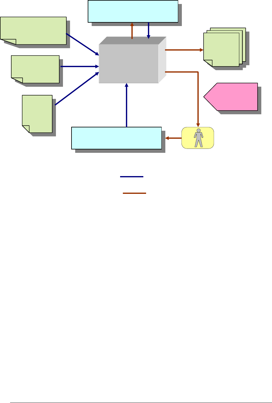
INTEROP Qualified Equipment Selection and Test Equipment ANNEX D
Date: 2006-06-27 Version 1.2 Page 76 of 84
The following diagram presents an overview of the inputs and outputs for interoperability test
system, including SUT behaviours observed by the operator which are partial results for final
verdict.
Figure D.4. Overview of Interoperability Test System
Model,
manufacturer,
version.
IS
and
IXIT
Test campaign options:
A. EUT-EUT
B. EUT-QE
INTEROPERABILITY
TEST
SYSTEM
Test
Reports
Script files containing execution
instructions for one or more test
cases. Created by the operator.
Test steps or
instructions to be
performed by the
operator
Test Operato
r
INPUTS
OUTPUTS
Output files containing echo of script
file and test results.

INTEROP Qualified Equipment Selection and Test Equipment ANNEX D
D.6 Test Equipment
The Test Equipment has the following requirements:
• Hardware required:
One PC with the requirements above:
- Pentium® 4 Processor (2.80 GHz)
- Hard Drive 80 GB
- 512MB RAM
- CD ROM
- RS-232 and USB 2.0 ports.
- Monitor with minimum resolution 1024x760
- Ethernet interface
• Software required:
- Microsoft Windows XP Professional-English version with the latest Service
Pack installed.
- Microsoft Office (English version)
- Test Manager (User Interface in the Test System manufactured by CETECOM).
- MS .NET Framework Runtime v1.1 or the .NET Framework SDK
- Perl programming environment
- Interrogator executables necessary to translate and run script text files
• Network switch or cross-over cable to connect PC to interrogator
• Additional physical and mechanical items needed for test cases execution
• Qualified equipments (see reference [11]):
- Interrogator devices
- Tag devices
Date: 2006-06-27 Version 1.2 Page 77 of 84
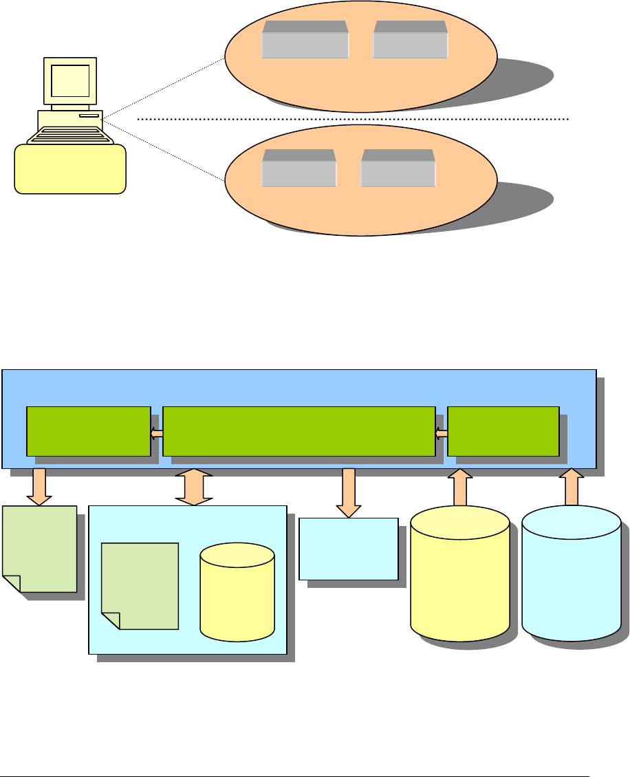
INTEROP Qualified Equipment Selection and Test Equipment ANNEX D
Date: 2006-06-27 Version 1.2 Page 78 of 84
System Architecture
D.7 Hardware Description
The hardware is composed of a PC, with the characteristics specified in section 4.3, and one of
the test scenarios which are described in detail in [11]. The Interoperability Test System will be
loaded and executed on the PC.
Inside the test scenario may be one or more Qualified Equipments, which are reference devices
for the implementation of the interoperability test cases. While being part of the SUT, the QE is
not have the main focus of the testing. The QE will have previously undergone conformance
(certified equipement) and interoperability testing. A QE may be an interrogator or a tag,
depending on the EUT.
Figure D.5. Hardware description
Software Description
D.8 Test Manager and Sequencer Modules
Interoperability
Test System
EUT1
EUT2
QE
EUT
SUT1
SUT2
Test Manager Module
Result
Analyzer
Project
Manager
Technologies
Manager
Project Data
Sequencer
Module
Project
Report
(Word)
TC
Result
Project
Values
(IS, IXIT,
Results…)
Technology
Versión
Definition
(IS, IXIT,
TC…
)
Script and
Output Files

INTEROP Qualified Equipment Selection and Test Equipment ANNEX D
Test Manager Module: Implements several management functions.
Technology manager
: Controls the different versions of the test platform and test cases.
Provides access to the technology database containing the IS, IXIT, test cases definition, etc.,
for the different technologies to test. It transfers the information to the Project Manager in order
to allow test selection, IS, IXIT editing, etc.
Project manager
:
The main characteristics are:
- This module is common to any technology.
- It performs the high level functions of the operation of the tester.
- It handles each individual test session,
- it controls the directories where the information will be stored,
- it allows the production of test reports or visualization of individual results,
- it drives the sequencer for the technology to be tested,
- it allows input of IS, IXIT and other session or device information
(manufacturer, model, etc.),
- it performs the test case mapping (i.e., the selection of applicable test cases).
Result analyser
: Records all verdicts providing filtering representation useful for debugging.
This is a software module with different functions that allow presentation of results with
different information filtering capabilities. I.e., view of produced test report, view of individual
test cases verdicts, set different filtering options, etc.
It also generates automatically the test reports for each test session. The report files are Word
documents.
These reports may contain:
• IS
• IXIT
• TEST CASE MAP
• STATIC CONFORMANCE REVIEW (SCR)
• TEST CASE RESULTS
The operator selects the desired reports to be generated and consulted.
Project Data
: Typically the user will create a test project (for each EUT) where all the
information related to the manufacturer of the equipment to be tested and the hardware/software
versions will be stored. A database will allow easy registration and recovery of already
performed test campaigns. Later the IS and IXIT information has to be entered and this provides
the necessary information for performing the test case selection. The operator can fill in this
data in a normal Microsoft Office Excel sheet (using a standardized sheet), which can be
imported by the test system or directly in the test system.
The operator can create, delete, save and modify projects. The project data may contain the
following information:
• EUT Data: All information that need to appear in the reports generated by the
application such as model, serial number, manufacturer, etc.
• IS Edition: with the information of capabilities and profiles supported by the
Equipment Under Test (EUT). The data edited into this area will affect to the list of
applicable test cases. The SCR (Static Conformance Review) is also available for
checking the proper IS edition.
Date: 2006-06-27 Version 1.2 Page 79 of 84
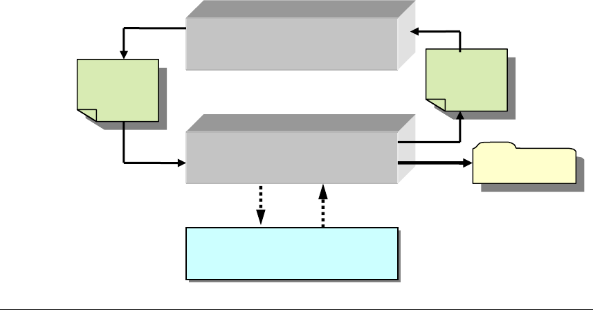
INTEROP Qualified Equipment Selection and Test Equipment ANNEX D
Date: 2006-06-27 Version 1.2 Page 80 of 84
• IXIT Edition: The data edited into this area will affect to the test cases execution.
IXIT data may be imported from an Excel file.
• General Parameters: This list is composed by the common parameters used by all of
the test cases.
• Test Cases: A test case is applicable or not applicable depending on the information
stored in IS proforma. The manual execution of an individual test case generates
several reports that can be checked by the operator.
• Test Campaign: A list of test cases to be sequentially executed by the operator. It can
be configured and saved by the operator.
• Script and Output Files: Input script files contain a list of consecutive directives that
configure and execute test cases on the interrogator. Each directive is echoed to the
output file along with the results of the directives. The Output File is processed by the
Test Manager to create a test report. The Script File can be created, edited and saved by
the operator using any text editor.
Sequencer Module: This module performs the sequencing of the different test steps of the
individual test cases or processes the Output File. The Test Manager Module uses the Sequencer
Module to execute an internal script. This script contains information about parameters and test
cases to execute and has a XML file format.
By clicking on any applicable test case of the list, a new window will appear with the steps to
execute the selected test case. The user can easily follow the execution flow with the help of this
window. It is necessary that operator uses in parallel the interrogator device software (which
shall be provided by the client) to execute the test case. Partial results and verdicts will need to
fill in manually by the user.
For each individual test case is executed, the Sequencer will generate a session folder (the folder
name contains the date and time of execution). In this folder will be stored the result files.
When the Sequencer finishes the script execution, generates a resume report file (in XML
format) with data related to each test case execution (verdict, start time, duration, etc.).
While the Sequencer is active, the Test Manager Module remains in background until the user
decides to exit from the Sequencer Module. At this point, Test Manager wakes up and reads the
report script file in order to update the results database.
Test Manager
Sequencer
Test Case or Script File and
companion Output File
Test Case
Results
Script
(
XML
)
Report
(
XML
)

INTEROP Qualified Equipment Selection and Test Equipment ANNEX D
Test Manager-Sequencer interface.
1. Test ManagerÆ Sequencer
When Test Manager launches the Sequencer, it must specify an internal script to execute as an
argument. This Sequencer argument will be the internal script full file path. The Test Manager
generates the internal script with the information contained in the project database and the user
selection. This XML file contains information about the test session, general parameters (IS,
IXIT), and the test cases for running.
The internal script xml structure is shown in the following figure:
1
2
3
4
5
6
7
8
9
10
11
12
13
14
15
16
17
18
19
20
21
22
23
24
25
26
27
28
29
30
<?xml version="1.0" encoding="ISO-8859-1"?>
<TestSession EUTName=" "
ReportFilename=""
Layer=""
DemoMode="" >
<CommonParameters>
<Parameter Index=""
BlockID=""
Name=""
Caption=""
Type=""
Value=""
Second_Value=""
Unit=""
Visible=""
Printable="" />
</CommonParameters>
<TestCaseList>
<TestCase ID=""
Name=""
Title=""
ResultFilename=""
TesterFilename=""
EstimatedTime=""
Conformance="">
<Parameters><Parameters />
<Results></Results>
</TestCase>
</TestCaseList>
</TestSession>
Line 1: This is the xml document header.
Tag: <TestSession>
Line 2-5: This is the internal script root. These fields contain information about the current
internal script.
Tag: <CommonParameters>
Line 6-17: This node contains a set of parameters used by all test cases in the internal script.
No fields are defined in this tag.
Tag: <Parameter>
Line 7-16: Defines a parameter item.
Date: 2006-06-27 Version 1.2 Page 81 of 84

INTEROP Qualified Equipment Selection and Test Equipment ANNEX D
Tag: <TestCaseList>
Line 18-29: This node contains a set of test cases to be executed.
No fields are defined in this tag.
Tag: <TestCase>
Line 19-28: Defines a test case item.
2. SequencerÆ Test Manager
The sequencer generates two types of output files:
a) The internal script result file.
b) The test case result files.
Test Manager only needs to read the final internal script result file.
An example of the file structure is described below:
1
2
3
4
5
6
7
8
9
<?xml version="1.0" standalone="yes" ?>
<TESTCASELIST>
<TESTCASE Ref=“6.3.1.2.1"
Date="2005-02-07T13:06:07"
Duration='00:00:12'
Verdict='PASS'
ResultPath="C:\Sequencer\Results\Session 2005-02-07 13.06.07\Result.6.3.1.2.1.xml" />
</TESTCASELIST>
<TESTCASELIST> tag may contain many <TESTCASE> tags as test cases have in the
internal script. Note that if a test case is executed more than once, only the last will be stored. In
addition, if some test cases are not executed, their Verdict field will be empty.
Ref This reference is assigned by CETECOM and it is only used by the
Test Manager
Date Test case execution start date and time.
Duration Test case execution time in hh:mm:ss format.
Verdict Test case final result.
ResultPath Main test case result file.
D.9 Running Individual Test Cases
A Windows Application appears and takes the control of the tester system when sequencer
launches an interoperability test case. In this window, the instructions to perform the selected
test case will be successively shown as the operator clicks on the “Next” button of the
application. These steps explain how the operator must to act on the devices.
During the test case execution, the operator may be required to answer a question or to insert a
data. Comments and observations about the test case execution may be inserted, too. All the
information as well as the answers remains on the left side of the window, in order to check the
performed steps.
Date: 2006-06-27 Version 1.2 Page 82 of 84
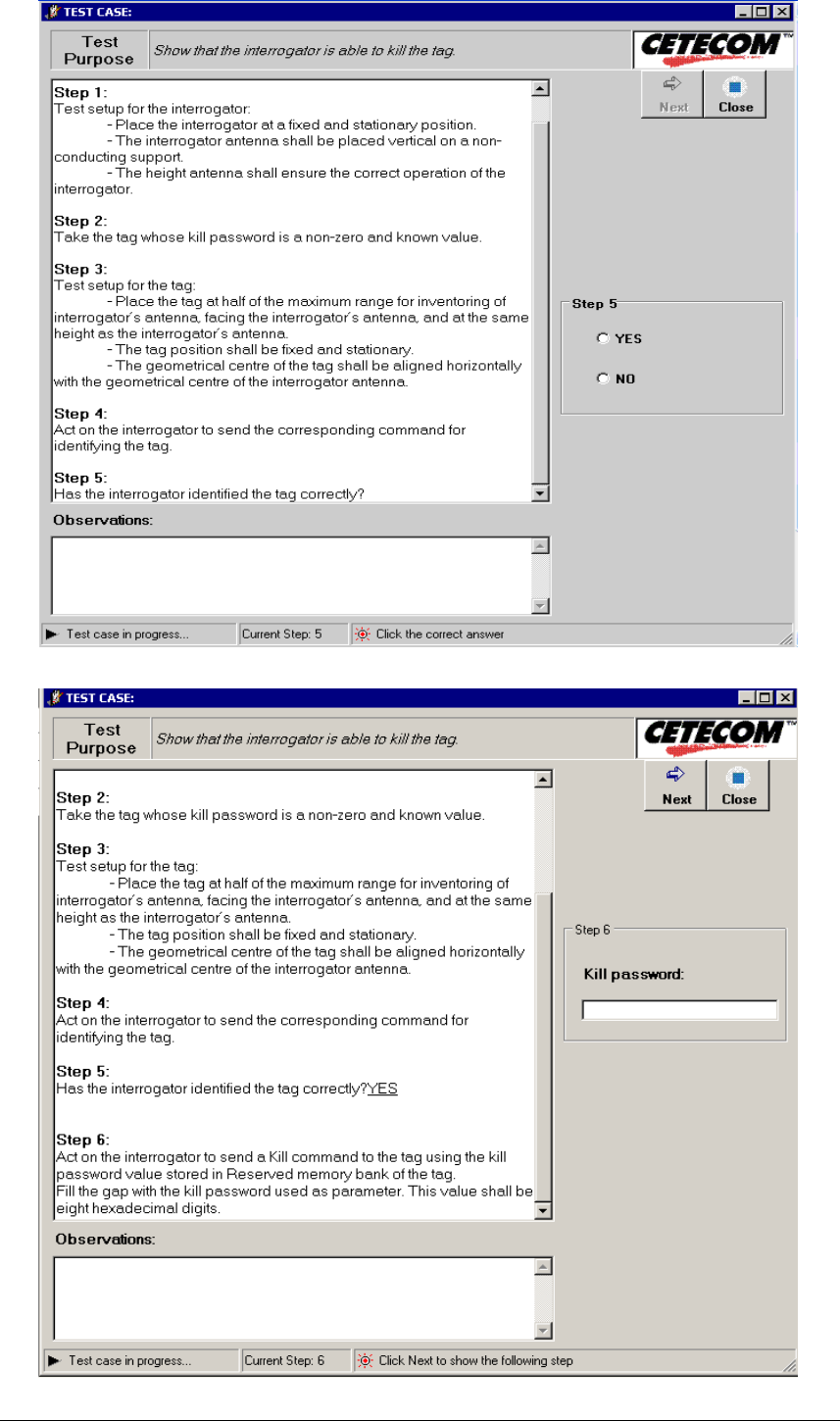
INTEROP Qualified Equipment Selection and Test Equipment ANNEX D
Date: 2006-06-27 Version 1.2 Page 83 of 84
INTEROP Qualified Equipment Selection and Test Equipment ANNEX D
Date: 2006-06-27 Version 1.2 Page 83 of 84
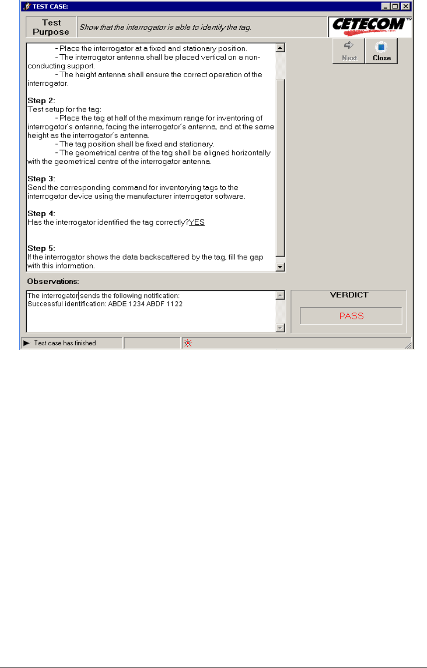
INTEROP Qualified Equipment Selection and Test Equipment ANNEX D
Date: 2006-06-27 Version 1.2 Page 84 of 84
When the test case has finished, the application elaborates the test case verdict, based on the
information inserted by the operator. Clicking the “Close” button, the application returns the
control to the sequencer module.
As result, the application generates a XML document with the information necessary to
elaborate the reports. An example of this XML file is shown:
